
Accident monitoring method in welldrilling process

A kind of accident and drilling technology, which is applied in drilling equipment, automatic drilling control system, earthwork drilling and production, etc. It can solve the problem of failure to consider the amount of mud disturbance, the inability to obtain the abnormal change of circulating mud, and the inability to ensure the accuracy of overflow leakage alarm Reliability and other issues, to achieve the effect of accurate and reliable leakage alarm

Inactive Publication Date: 2010-04-21
HUBEI UNIV OF TECH
View PDF2 Cites 29 Cited by
  • Summary
  • Abstract
  • Description
  • Claims
  • Application Information

AI Technical Summary

Problems solved by technology

Aiming at the safety problems of drilling operations, the existing patented technology "well kick and lost circulation monitoring instrument" (application number: 89208768.4) realizes the monitoring and alarming of lost circulation and overflow, and there is another patented technology "monitoring the tripping process of the drilling site and Automatic Grouting Control Method” (Application No.: 200710172833.6) uses the CAN bus in combination with other drilling instruments to realize tripping leakage and overflow monitoring and automatic grouting control. However, these patents have not established a complete drilling accident model and They do not take into account the disturbance of the mud in the mud tank caused by the start and stop of the high-pressure pump and the replenishment of glue, etc., so they cannot obtain the total amount of circulating mud during the drilling process except for known factors. Abnormal changes in volume, in fact, the accuracy and reliability of overflow lost circulation alarm cannot be guaranteed without identification of drilling conditions and perfect data storage

Method used


Image

  • Accident monitoring method in welldrilling process
  • Accident monitoring method in welldrilling process
  • Accident monitoring method in welldrilling process

Examples


Embodiment Construction

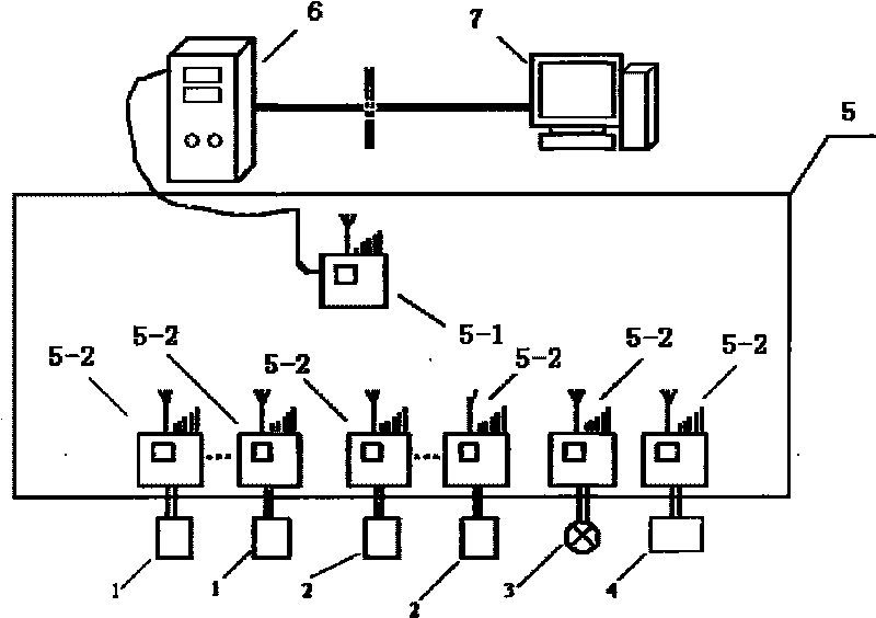
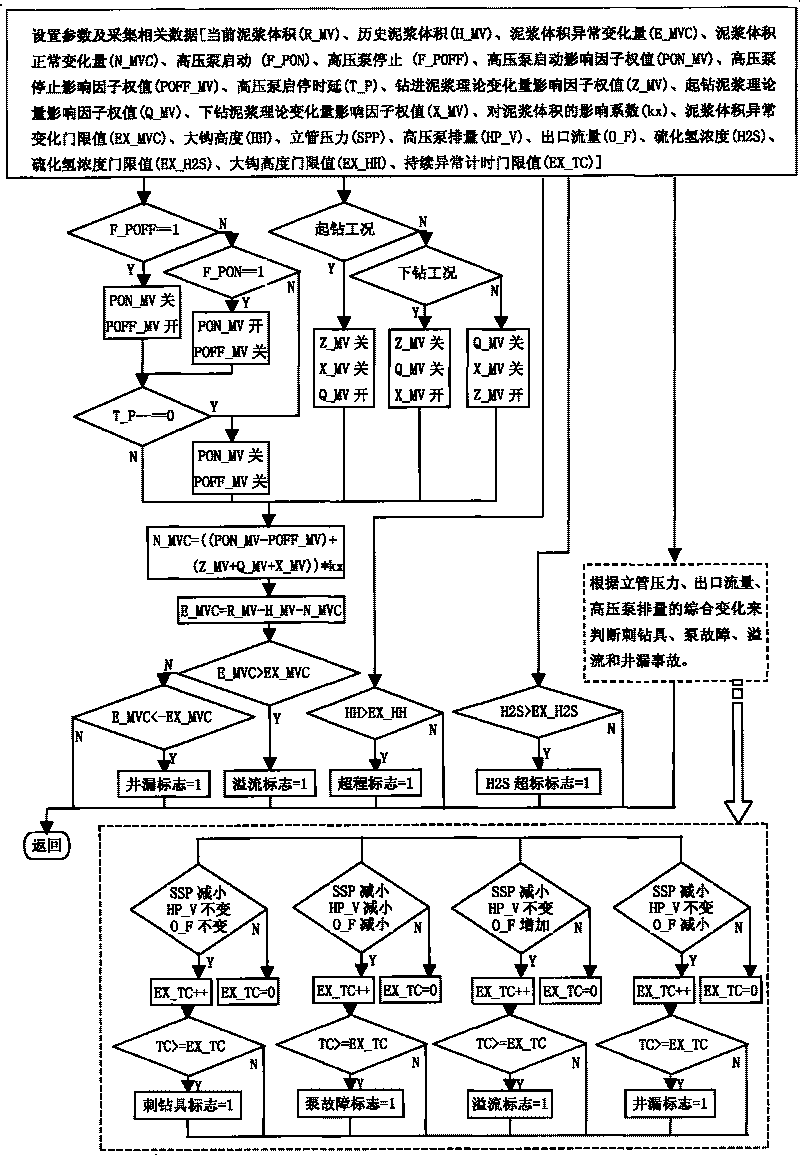
[0022] A method for monitoring accidents in the drilling process. The accidents include lost circulation and overflow. The difference is that the alarm judgment of the lost circulation and overflow is based on the total volume of mud in the circulating mud tank through the working condition identification model and the alarm model. The abnormal changes of the mud are monitored, and when the change of the total volume of the mud exceeds the alarm threshold value of lost circulation or overflow, a corresponding alarm is given.

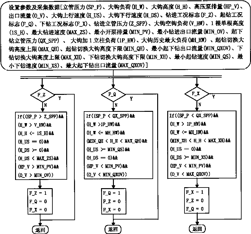
[0023] Specifically, the working condition recognition model automatically recognizes three working conditions of drilling, tripping out and tripping in through analyzing and processing drilling parameters.

[0024] Specifically, the interlocking among the three working conditions is realized through working condition flags, and the data processing model is automatically switched according to the detected switch between the working conditions.

[0025] T...


PUM


Abstract

The invention relates to the technical field of production safety monitoring in petroleum and natural gas drilling engineering, in particular to an accident monitoring method in the welldrilling process. The accidents comprise leakage and overflow, and the difference of the accident monitoring method lies in that: the alarm judgment of the leakage and the overflow is that the abnormal change of the total volume of the mud in a circular mud tank is monitored by an operating condition identifying model and an alarm model, and a corresponding alarm is given when the change of the total volume of the mud exceeds an alarm threshold of the leakage and the overflow. The accident monitoring method in the welldrilling process can judge the occurrences of alarm accidents, such as the leakage, the overflow and the like, accurately and reliably by monitoring drilling engineering parameters in real time.

Description

technical field [0001] The invention relates to the technical field of production safety monitoring of oil and gas drilling engineering, in particular to a drilling process accident monitoring method. Background technique [0002] Drilling engineering is a high-risk operation, and the research on automatic identification of drilling process conditions and engineering accident monitoring methods has always been an important topic for drilling safety. Aiming at the safety problems of drilling operations, the existing patented technology "well kick and lost circulation monitoring instrument" (application number: 89208768.4) realizes the monitoring and alarming of lost circulation and overflow, and there is another patented technology "monitoring the tripping process of the drilling site and Automatic Grouting Control Method” (Application No.: 200710172833.6) uses the CAN bus in combination with other drilling instruments to realize tripping leakage and overflow monitoring and a...

Claims


Application Information

Patent Timeline
IPC IPC(8): E21B44/00E21B21/08E21F17/18
Inventor 杨光友黄兴华中平苏旭武张道德张铮
Owner HUBEI UNIV OF TECH
Learn More