
Light guide plate and backlight module provided therewith

A technology of backlight module and light guide plate, which is applied in the field of light guide plate, can solve the problems of uneven brightness of light guide plate, achieve the effect of increasing incident rate, increasing light receiving area, and improving visible area

Inactive Publication Date: 2010-04-14
RADIANT OPTO ELECTRONICS NANJING
View PDF0 Cites 13 Cited by
  • Summary
  • Abstract
  • Description
  • Claims
  • Application Information

AI Technical Summary

Problems solved by technology

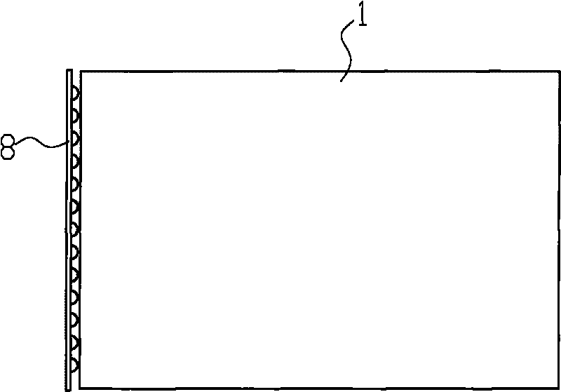
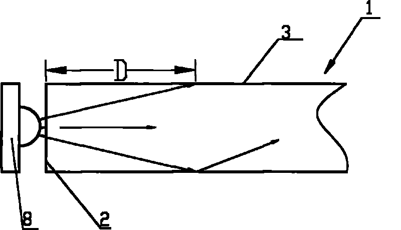
[0006] The purpose of the present invention is to provide a new type of light guide plate and backlight module, which can improve the light receiving rate of the light guide plate and solve the problem of uneven brightness existing in ordinary light guide plates

Method used


Image

  • Light guide plate and backlight module provided therewith
  • Light guide plate and backlight module provided therewith
  • Light guide plate and backlight module provided therewith

Examples


Embodiment Construction

[0031] Embodiments of the present invention will be described in detail below with reference to the accompanying drawings.

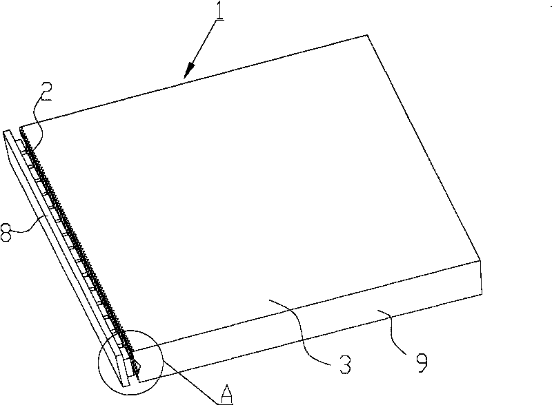
[0032] attached image 3 It is a schematic diagram of the backlight module of the present invention, which includes: a light guide plate 1 and a light bar 8 disposed on at least one side of the light guide plate 1 , and the light bar 8 has a plurality of LED light sources. Specifically, the light guide plate 1 has:

[0033] A light receiving surface 2, the light receiving surface 2 is opposite to the light strip 8;

[0034] The light-emitting surface 3 is adjacent to the light-receiving surface 2, and the light-emitting surface 3 is opposite to the liquid crystal display;

[0035] And a plurality of side surfaces 9 and bottom surfaces connecting the light receiving surface 2 and the light emitting surface 3, the side surfaces 9 and bottom surfaces are coated or attached with reflective materials.

[0036] In order to improve the uniformity of the ligh...


PUM


Abstract

The invention relates to a light guide plate and a lateral incident type backlight module. The light guide plate is provided with a light receiving surface which is opposite to a light source and positioned on at least one side of the light guide plate, and a light emergent surface adjacent to the light receiving surface, wherein the light receiving surface is provided with a plurality of horizontal grooves or horizontal embossed strips extending along the thickness direction of the light guide plate; the plurality of horizontal grooves or horizontal embossed strips are arranged along the length direction or width direction of the light guide plate; and the light receiving surface is also provided with longitudinal grooves or longitudinal embossed strips extending along the length direction or width direction of the light guide plate. In the invention, a light beam emitted from the LED light source is incident into the light guide plate and then a divergence angle of the light beam is increased or maintained, so as to shorten a dark band on the light emergent surface of the light guide plate, and increase a visible area of a liquid crystal display; in addition, the longitudinal grooves or longitudinal embossed strips are additionally arranged, so that the structure of the light receiving surface of the light guide plate can be more complicated, and the light receiving area of the light guide plate is increased, thus further improving the rate of incidence of light rays, and the light emitting uniformity of the backlight module.

Description

technical field [0001] The invention relates to a light guide plate used for liquid crystal displays or liquid crystal televisions, and a backlight module with the light guide plate. Background technique [0002] With the advent of the information age, the development of liquid crystal displays (LCDs) has advanced by leaps and bounds. The current backlight module is usually composed of a light guide plate, a diffusion sheet, a prism sheet, a reflector, and a light-emitting element (LED or CCFL, cold cathode lamp) and the like. Traditional backlight modules usually use CCFL light sources, but this light source has problems such as high power consumption, high starting voltage, short service life, and the presence of harmful substances such as mercury, and has been gradually eliminated by the market. [0003] It is replaced by LED light-emitting components. Using LED as a light source has the advantages of low power consumption, stable light emission, long service life, no ha...

Claims


Application Information

Patent Timeline
Patent Type & Authority Applications(China)
IPC IPC(8): F21V8/00F21S8/00G02F1/13357F21Y101/02F21Y103/10F21Y115/10
Inventor 张智强司群英陆韦中
Owner RADIANT OPTO ELECTRONICS NANJING
Learn More