Formwork support system for steel frame structure cast-in-place concrete floorslabs

A formwork support and concrete technology, which is applied to the preparation of building components on site, formwork/formwork/work frame, building construction, etc., can solve the problems of slowing down construction progress, slow construction progress, and large steel consumption, and achieve faster Construction progress, effect of reducing on-site workload

Inactive Publication Date: 2010-04-14
ZHEJIANG UNIV
View PDF5 Cites 5 Cited by
  • Summary
  • Abstract
  • Description
  • Claims
  • Application Information

AI Technical Summary

Problems solved by technology

[0004] 1) Ordinary cast-in-place concrete floor slabs need to install a large number of formwork supports on the floor, and the construction progress is slow
[0005] 2) The profiled steel plate needs to be equipped with end anchors, which increases the complexity of construction
[0006] 3) If it is necessary to consider the combined effect of profiled steel plate and concrete floor slab, in addition to adopting a special form or special structure, there are also requirements for the durability and fire protection of the steel plate; otherwise, the steel plate is only used as a formwork during the construction of the floor slab, and it will lose its effect after the construction is completed. , consume a large amount of steel
[0007] 4) The profiled steel plate cannot bear the unhardened concrete load and construction load alone, and it is necessary to set up temporary vertical supports between spans, including support trusses and steel pipe top supports supported on the floor, which slows down the construction progress and increases material costs

Method used


Image

  • Formwork support system for steel frame structure cast-in-place concrete floorslabs
  • Formwork support system for steel frame structure cast-in-place concrete floorslabs
  • Formwork support system for steel frame structure cast-in-place concrete floorslabs

Examples


Embodiment Construction

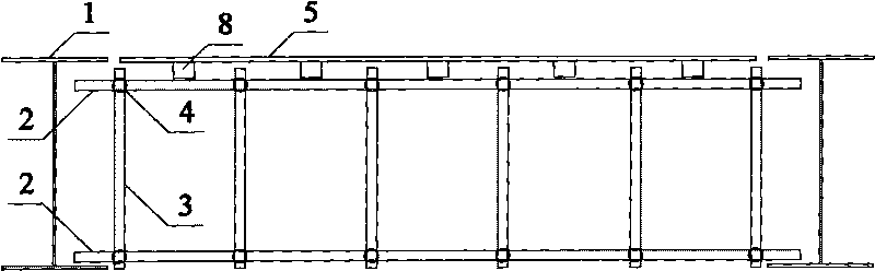
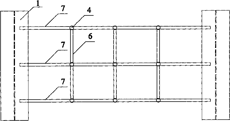
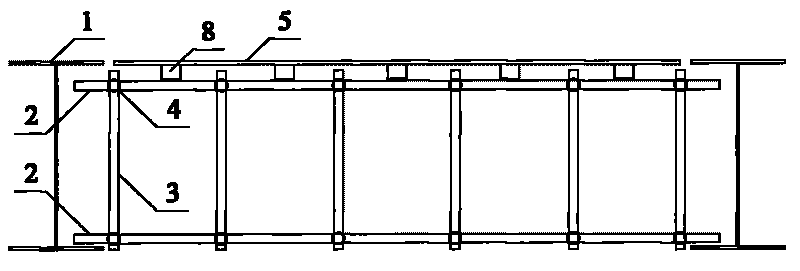
[0018] The formwork support system for cast-in-place concrete slabs of steel frame structures includes I-shaped section beams 1, horizontal scaffolding steel pipes 2, vertical scaffolding steel pipes 3, steel pipe fasteners 4, wooden formwork 5, tie rod steel pipes 6, and corrugated wood 8; Two horizontal scaffolding steel pipes 2 and multiple vertical scaffolding steel pipes 3 are connected by steel pipe fasteners 4 to form a scaffolding steel pipe truss 7. Scaffolding steel pipe trusses 7 with more than 2 poles are connected with more than two tie rod steel pipes 6 through steel pipe fasteners 4. Scaffolding steel pipes The lower end of the truss 7 is placed on the lower flange of the I-shaped cross-section beam 1, the upper end of the steel pipe truss 7 of the scaffolding is placed with corrugated wood 8, and the wooden formwork 5 is placed on the corrugated wood 8.

[0019] When the distance between two adjacent I-shaped cross-section beams 1 is less than 3 meters, the dist...


PUM


Abstract

The invention discloses a formwork support system for steel frame structure cast-in-place concrete floorslabs. The formwork support system comprises I-shaped section beams, horizontal scaffold steel pipes, vertical scaffold steel pipes, steel pipe fasteners, timber formworks, tie bar steel pipes and battens; two horizontal scaffold steel pipes and a plurality of vertical scaffold steel pipes are connected by the steel pipe fasteners to form scaffold steel pipe trusses; more than two scaffold steel pipe trusses are connected with more than two tie bar steel pipes by the steel pipe fasteners; the lower ends of the scaffold steel pipe trusses are arranged on the lower flanges of the I-shaped section beams, the battens are arranged on the upper ends of the scaffold steel pipe trusses, and the timber formworks are arranged on the battens. Compared with the background art, the invention has the advantages: 1) the timber formworks are used for freely fabrication and assembly; 2) steel pipe top bracings are avoided, thereby reducing the site work load; and 3) the formworks are supported on the lower flanges of the beams, thereby providing wide working platforms for the operations of all types of work, and realizing multilayer stereo operation to further accelerate the construction progress.

Description

technical field [0001] The invention relates to the field of construction, in particular to a formwork support system for cast-in-place concrete floors with steel frame structures. Background technique [0002] Multi-high-rise buildings adopt steel structures, which have the advantages of light weight, good seismic performance, fast construction speed, and low environmental pollution. The use of steel structures in multi-high-rise buildings in my country is becoming more and more common. At present, ordinary cast-in-place concrete slabs and profiled steel-cast-in-place concrete composite slabs are widely used in steel frame structures. [0003] But it also has the following problems: [0004] 1) Ordinary cast-in-place concrete floor slabs need to install a large number of formwork supports on the floor, and the construction progress is slow. [0005] 2) The profiled steel plate needs to be equipped with end anchors, which increases the complexity of construction. [0006]...

Claims


Application Information

Patent Timeline
IPC IPC(8): E04G11/48
Inventor 张成吴慧岑迪钦陈强
Owner ZHEJIANG UNIV
Why Eureka
Try Eureka