
Construction control device for pedestal pre-embedded steel plates of pre-stressed concrete box girder

A technology of pre-embedded steel plates and support steel plates, applied in bridges, bridge construction, erection/assembly of bridges, etc., can solve the problems that the construction site is difficult to meet the construction progress requirements, affects the quality of the box girder, and is prone to loosening

Active Publication Date: 2010-04-07
THE 5TH ENG MBEC
View PDF0 Cites 11 Cited by
  • Summary
  • Abstract
  • Description
  • Claims
  • Application Information

AI Technical Summary

Problems solved by technology

When using this method to fix the pre-embedded steel plate of the support, there are the following problems: 1. It is easy to deform the pre-embedded steel plate of the support during the construction process, and it is difficult to meet the specification requirements
2. The construction period is long, and it is difficult to meet the construction progress requirements on the construction site with tight construction period requirements
3. It is easy to loosen during the hoisting of the main structure steel bars, concrete pouring and vibration, which affects the quality of the box girder and increases the post-processing cost of the box girder

Method used


Image

  • Construction control device for pedestal pre-embedded steel plates of pre-stressed concrete box girder
  • Construction control device for pedestal pre-embedded steel plates of pre-stressed concrete box girder
  • Construction control device for pedestal pre-embedded steel plates of pre-stressed concrete box girder

Examples


Embodiment 1

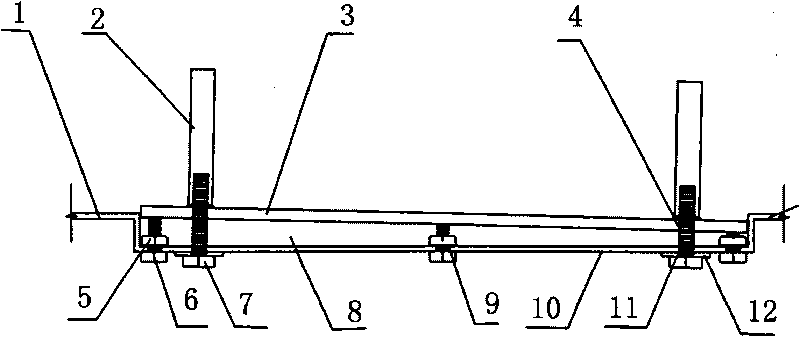
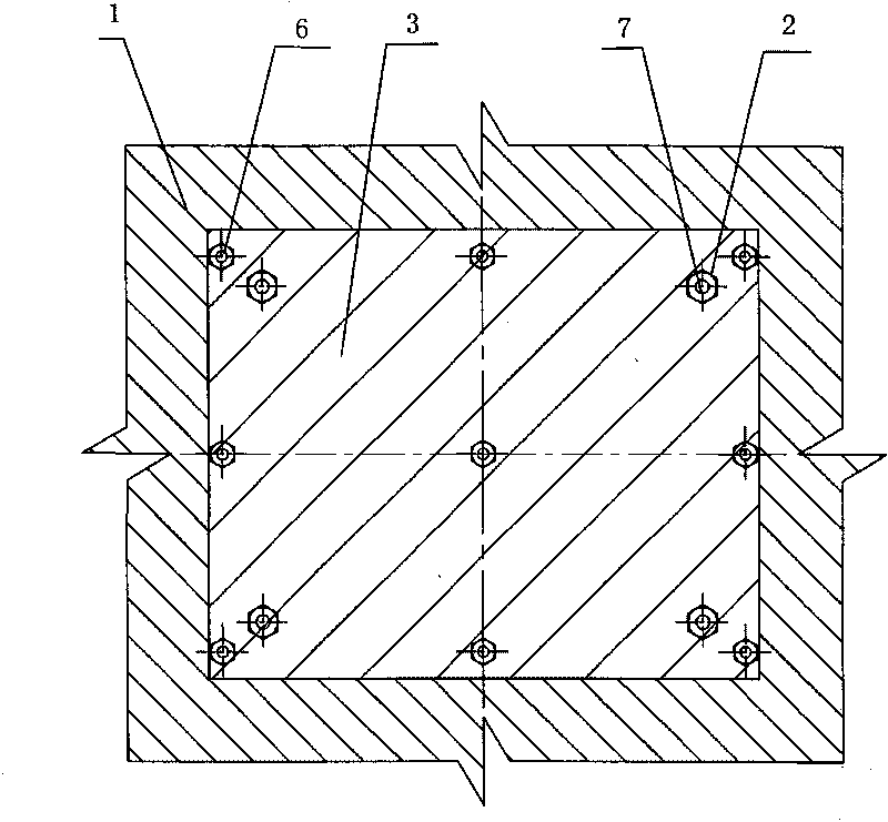
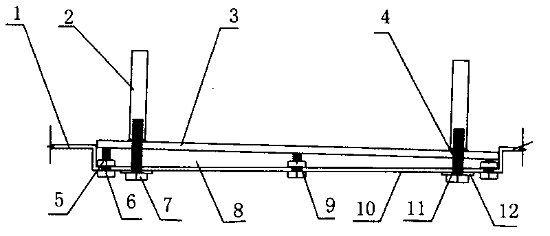
[0011] The present invention comprises basin-shaped box girder bottom mold support steel plate 1, on each of the four corners of the groove bottom plate 12 of box girder bottom mold support steel plate 1, an upper limit hole 11 is processed, and on the box girder bottom mold support steel plate A total of nine lower limit holes 9 in three rows and three columns are evenly processed on the groove bottom plate 12 of 1, and a positioning hole is fixed on the upper surface of the groove bottom plate 12 of the box girder bottom mold support steel plate 1 and above each lower limit hole 9. The nut 5, the support pre-embedded steel plate 3 with the same cross-sectional size as the groove bottom plate 12 of the box girder bottom form support steel plate 1 is placed in the groove 8 of the box girder bottom form support steel plate 1, and is embedded in the support On the steel plate 3, a pre-embedded sleeve hole 4 is processed at the position corresponding to the upper limit hole 11 of ...

Embodiment 2

[0014] The structure of embodiment 2 is basically the same as that of embodiment 1, the difference is:

[0015] Four rows and five rows of nine lower limit holes 9 are evenly processed on the groove bottom plate 12 of the box girder bottom mold support steel plate 1 .


PUM


Abstract

The invention discloses a construction control device for pedestal pre-embedded steel plates of a pre-stressed concrete box girder, which comprises a basin-shaped box girder bottom mould pedestal steel plate. The construction control device is characterized in that: the pedestal pre-embedded steel plates with the same structure are placed in a groove of the box girder bottom mould pedestal steel plate so as to limit the horizontal displacement of the pedestal pre-embedded steel plates; a plurality of vertically-downward limiting adjusting bolts tightly withstand the pedestal pre-embedded steel plates upwards; and four pedestal anchor bolts tighten the pedestal pre-embedded steel plates downwards so as to limit the vertical displacement of the pedestal pre-embedded steel plates. The construction control device mainly realizes the slope adjustment of the pedestal pre-embedded steel plates through the tightening and releasing of the bolts, and the elongations of the bolts can be controlled precisely, so that the slopes of the pedestal pre-embedded steel plates are adjusted precisely and the construction quality is ensured. The construction control device for the pedestal pre-embedded steel plates of the pre-stressed concrete box girder has strong adaptability, simple construction, convenient operation, high operation efficiency and high stability in various box girder prefabrication yards.

Description

technical field [0001] The invention relates to prestressed concrete box girder construction equipment, in particular to a prestressed concrete box girder support pre-embedded steel plate construction control device. Background technique [0002] With the comprehensive and rapid development of my country's economy and society, my country's construction industry has developed unprecedentedly, and infrastructure construction has blossomed all over the country. The construction of cross-river and sea-crossing bridges has become an inevitable development trend of my country's road network construction. The whole hole prefabrication and whole hole erection The construction technology has been widely used in the construction of major bridges. In the prefabrication process of the box girder, the pre-embedding of the steel plate of the support is a necessary construction process. The most common construction method is to pre-embed the support with wooden strips before hoisting the ste...

Claims


Application Information

Patent Timeline
IPC IPC(8): E01D21/00
Inventor 李兰祖彭建萍鲁军明刘为林刘合茂赵则锋范大意朱能杰胡利宾王涛侯培军陈巧芬
Owner THE 5TH ENG MBEC
Learn More