
Bidirectional DC/DC converter

A DC converter and terminal technology, applied in output power conversion devices, conversion equipment with intermediate conversion to AC, conversion of DC power input to DC power output, etc., can solve the voltage value that cannot be reduced in voltage value and bidirectionally converted. Limitation, boost voltage upper limit, etc.

Active Publication Date: 2010-03-31
SHINDENGEN ELECTRIC MFG CO LTD
View PDF2 Cites 11 Cited by
  • Summary
  • Abstract
  • Description
  • Claims
  • Application Information

AI Technical Summary

Problems solved by technology

[0008] However, in the bidirectional DC / DC converter shown in Patent Document 1, there is a problem that the voltage value capable of bidirectional conversion is limited depending on the turns ratio between the primary side and the secondary side of the transformer, and in particular During the boost operation, the upper limit of the boost voltage is limited according to the voltage value of the low voltage side
[0011] Furthermore, during the boost operation, when the voltage value of the boosted voltage is lowered due to some abnormality on the high voltage side, the voltage value cannot be lowered to near 0V.

Method used


Image

  • Bidirectional DC/DC converter
  • Bidirectional DC/DC converter
  • Bidirectional DC/DC converter

Examples


Embodiment Construction

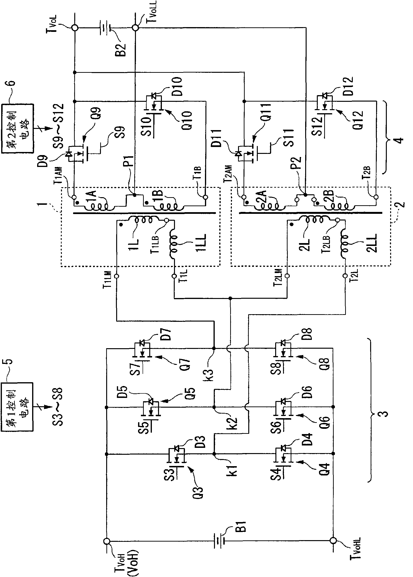
[0045] Hereinafter, a bidirectional DC / DC (Direct Current / Direct Current) converter according to one embodiment of the present invention will be described with reference to the drawings. figure 1 It is a schematic block diagram of the structure of the same embodiment.

[0046] Such as figure 1 As shown, the DC / DC converter based on the embodiment of the present invention is used at a high voltage V oH of battery B1 and the low voltage V oL Between the batteries B2, the one whose voltage value has decreased is supplemented with energy from the other, thereby suppressing the decrease in voltage value.

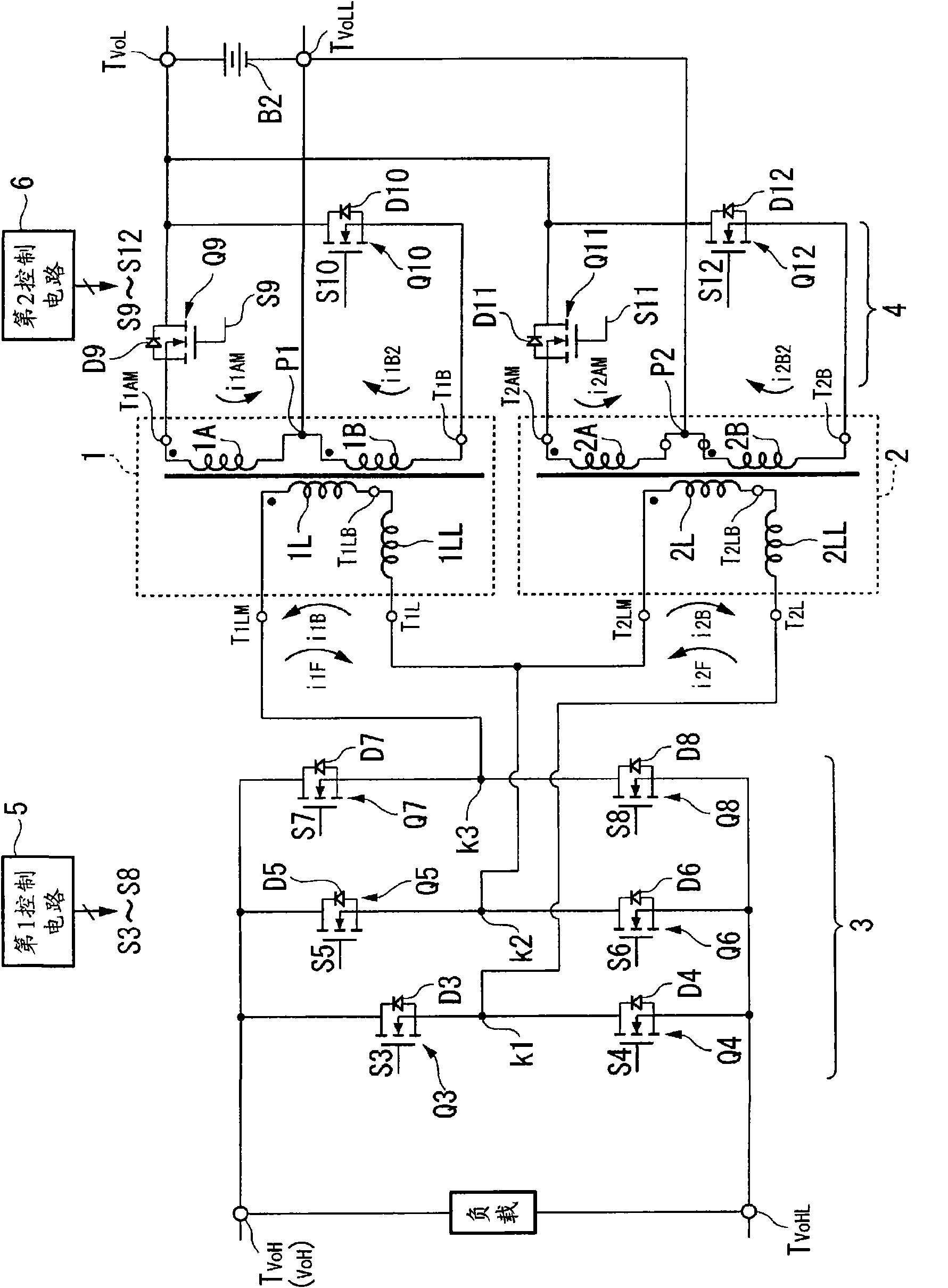
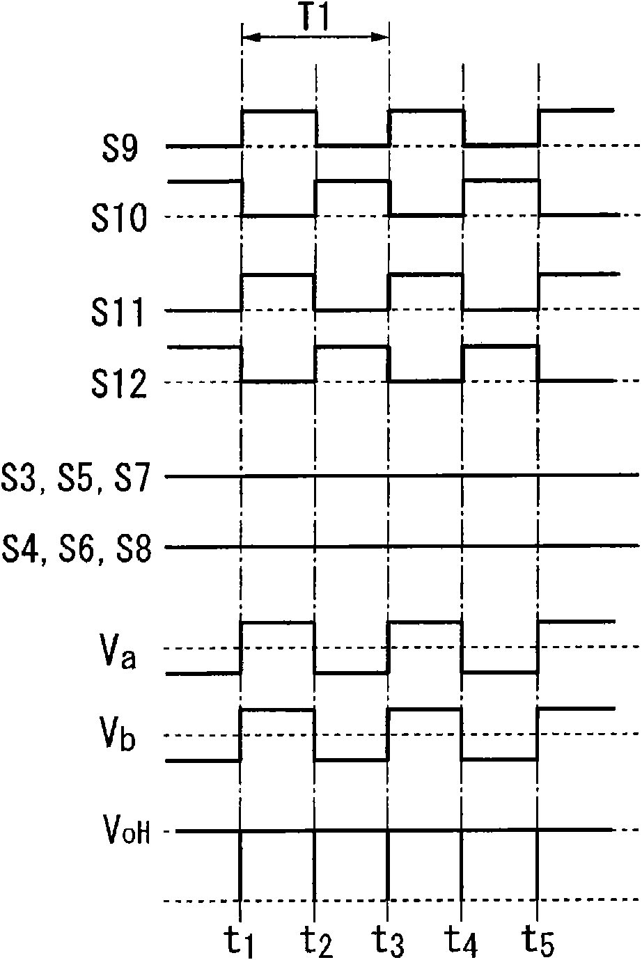
[0047] exist figure 1 In the bidirectional DC / DC converter of this embodiment, in the voltage conversion (energy conversion) of the step-up process, the secondary-side orthogonal conversion unit 4 converts the DC low voltage V in the battery B2 oL Partially converted to single-phase rectangular wave AC voltage. The primary side quadrature conversion unit 3 rectifies the sing...


PUM


Abstract

Provided is a bidirectional DC / DC converter which can control a boost voltage in a wide range. The DC / DC converter includes: three series circuits (3) formed by a first to a sixth switch (Q3 to Q8), each two of which are connected in series between a plus terminal and a minus terminal of a high voltage side; two transformers (1, 2) in which primary windings are connected in series and input terminals of the primary windings (T1LM, T1L, T2LM, T2L) are connected to connection points (K1 - K3) of the switching elements; and a seventh to a tenth switch (Q9 - Q12). The transformers have secondary windings, each of which is divided at the middle point (P1, P2). The middle points are connected to a minus terminal of a low voltage side. Respective terminals of the secondary windings (T1AM, T1B, T2AM, T2B) are connected to a plus terminal of the low voltage side by the seventh to the tenth switches (Q9 - Q12).

Description

technical field [0001] The present invention relates to a bidirectional DC / DC converter, in particular to a bidirectional DC / DC conversion capable of changing the voltage to a specified output voltage (decreasing the voltage or increasing the voltage) within a wide input voltage range device. [0002] The present invention claims priority to Japanese Patent No. 2007-171087 filed on June 28, 2007, and the content thereof is incorporated herein. Background technique [0003] Generally, a DC / DC converter adopts a configuration in which the voltage is lowered in one direction, that is, from a high-voltage side voltage to a low-voltage side voltage, or a configuration in which the voltage is increased from a low-voltage side voltage to a high-voltage side voltage. [0004] In a vehicle, there are two DC power supply systems using batteries having different voltage values ​​(high-side voltage and low-side voltage). [0005] Therefore, in vehicles seeking high efficiency, the fol...

Claims


Application Information

Patent Timeline
Patent Type & Authority Applications(China)
IPC IPC(8): H02M3/28
CPCH02J2007/0059H02M3/33584H02J7/0054H02J2207/20H02J7/342H02M3/28Y02B40/00
Inventor 多田信裕佐藤久夫
Owner SHINDENGEN ELECTRIC MFG CO LTD
Learn More