
Thermomagnetic power plant

A power device and thermo-magnetic technology, applied in the field of thermo-magnetic power device, can solve the problems of low energy utilization rate of internal combustion engine and complex mechanical structure, and achieve the effect of simple structure and high efficiency

Inactive Publication Date: 2010-03-31
方李明
View PDF0 Cites 10 Cited by
  • Summary
  • Abstract
  • Description
  • Claims
  • Application Information

AI Technical Summary

Problems solved by technology

[0003] In order to overcome the problems of low energy utilization rate and complex mechanical structure of internal combustion engines in the prior art,

Method used


Image

  • Thermomagnetic power plant
  • Thermomagnetic power plant
  • Thermomagnetic power plant

Examples


no. 1 approach

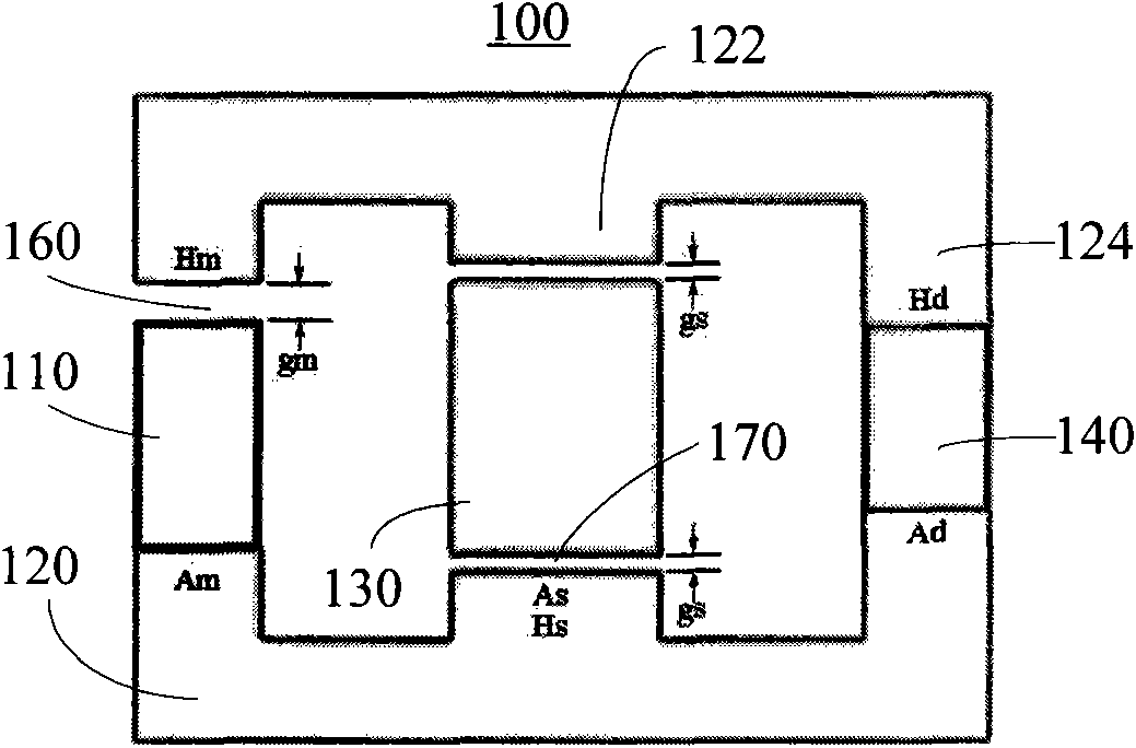
[0060] Such as Figure 4 , 5 Shown are the front view and perspective view of the first embodiment of the thermomagnetic motor of the present invention, respectively. The thermomagnetic motor 30 mainly includes a first stator 31 , a second stator 32 , a third stator 33 and a rotor 34 . The first stator 31, the second stator 32 and the third stator 33 are respectively fixed on the housing (in order to simplify the structure, Figure 4 , 5 not shown in). The first stator 31, the second stator 32 and the third stator 33 are all composed of the same components. Taking the first stator 31 as an example, it mainly includes a first stator magnet 311, a first stator yoke 312, two first stator salient poles 3123 and two oppositely disposed on the first stator yoke 312. 3125, and the first stator thermal magnet 314. There is a rotor air gap 343 between the rotor 34 and the first stator salient poles 3123 and 3125 .

[0061] In a preferred embodiment, there is a gap 316 between th...

no. 2 approach

[0080] Such as Figure 12 , 13 Shown are the front view and perspective view of the second embodiment of the thermomagnetic motor of the present invention, respectively. In this embodiment, the thermomagnetic motor 40 includes stators 41 , 42 , 43 and a rotor 44 . The stators 41, 42, and 43 have the same structure, and the stator 41 is taken as an example to illustrate its structural composition. Similar to the structure of the first embodiment of the present invention, the stator 41 mainly includes a first stator magnet 411, a first stator yoke 412, and two first stator protrusions that are oppositely arranged on the first stator yoke 412. Magnetic poles 4123 and 4125 , and first stator thermomagnet 414 . Wherein the stator magnet 411 can be a permanent magnet or an electromagnet instead. A gap 416 is provided at both ends or one end of the stator magnet 411, and the gap 416 can be filled with materials with relatively low magnetic permeability such as air, copper, and al...


PUM


Abstract

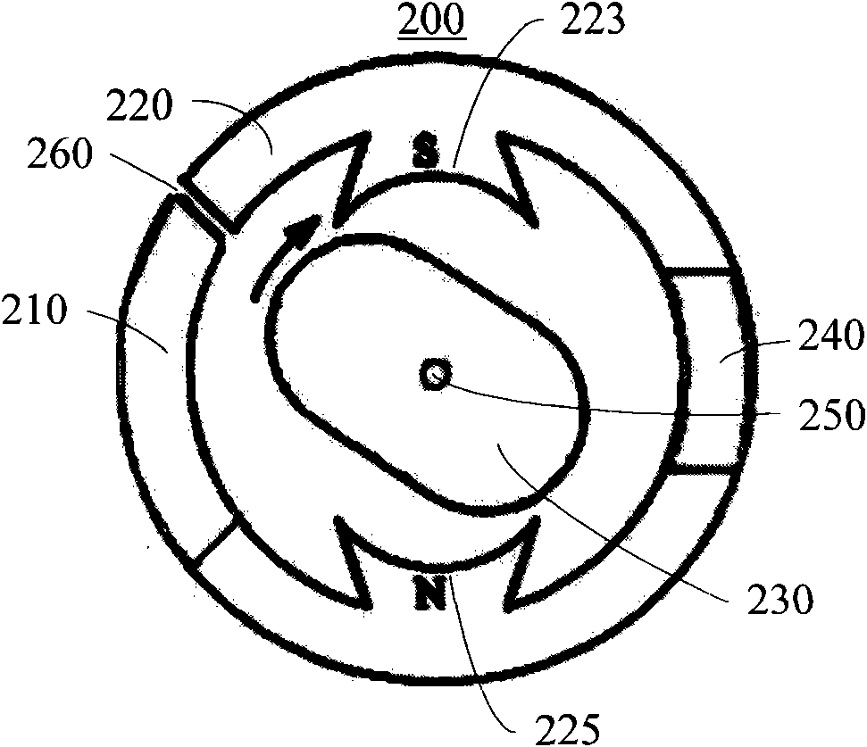
The invention provides a thermomagnetic power plant, comprising a magnetic yoke, a magnetic body, a magnetic conduction element and a thermomagnetic body. The magnetic body generates a magnetic field.The magnetic yoke guides the magnetic field to form a first magnetic path and a second magnetic path. The magnetic conduction element is arranged on the first magnetic path. The thermomagnetic body is arranged on the second magnetic path. When the temperature of the thermomagnetic body changes, the magnetic resistance of the second magnetic path changes and causes the magnetic flux of the first magnetic path to change accordingly. The invention, by adopting the structure, solves the problems of not high energy availability factor and complex mechanical structure of combustion engine in the prior art and provides a thermomagnetic power plant with simple structure and higher energy availability factor.

Description

【Technical field】 [0001] The invention relates to a thermomagnetic power device, in particular to a thermomagnetic power device applied in an engine. 【Background technique】 [0002] The current mainstream internal combustion engine is mainly composed of cylinders, pistons and crankshafts. The gas in the cylinder pushes the piston to do work when it is heated and expands, and the piston reciprocates in the cylinder due to the alternation of multiple cylinders or the use of an inertial turntable. A mechanism such as a crankshaft converts the reciprocating motion of the piston into circular motion. During the whole movement process, the mechanical structure is relatively complicated, and the kinetic energy consumed by friction is relatively large; at the same time, due to the inertia of the piston, a large part of the energy is also lost. In conclusion, for various reasons, the overall efficiency of today's internal combustion engines is relatively low. 【Content of inventio...

Claims


Application Information

Patent Timeline
IPC IPC(8): H02N11/00H02N10/00
Inventor 方李明
Owner 方李明
Learn More