
Light box structure with modular light source and modular light source structure thereof

A modular and light source technology, applied in the direction of light source, point light source, planar light source, etc., can solve the problems of general products without suitable structure, unable to uniformly emit light, and increase cost, so as to achieve easy heat dissipation, reduce production cost, and reduce usage Quantity effect

Active Publication Date: 2010-03-31
SINOLOGY ENTERPRISE
View PDF2 Cites 5 Cited by
  • Summary
  • Abstract
  • Description
  • Claims
  • Application Information

AI Technical Summary

Problems solved by technology

However, the light emitting direction of the direct-lit backlight unit cannot be changed, so it is not possible to achieve the effect of uniform light emitting in every direction.
In addition, each direct-type backlight unit needs to use a large number of light-emitting diodes, which will increase the cost and cause the problem of not being easy to dissipate heat
[0006] It can be seen that the above-mentioned existing light box structure and its light source structure obviously still have inconvenience and defects in structure and use, and need to be further improved urgently.
In order to solve the above-mentioned problems, the relevant manufacturers have tried their best to find a solution, but for a long time no suitable design has been developed, and the general product has no suitable structure to solve the above-mentioned problems. This is obviously the relevant industry. Urgent problem

Method used


Image

  • Light box structure with modular light source and modular light source structure thereof
  • Light box structure with modular light source and modular light source structure thereof
  • Light box structure with modular light source and modular light source structure thereof

Examples


Embodiment Construction

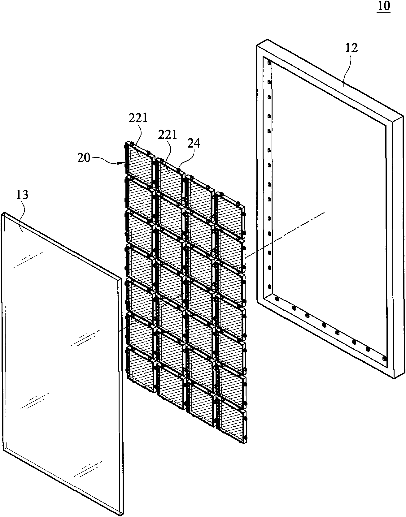
[0053] In order to further explain the technical means and effects of the present invention to achieve the intended purpose of the invention, the light box structure with a modular light source and its modular light source structure proposed according to the present invention will be described in detail below in conjunction with the accompanying drawings and preferred embodiments. Embodiments, structures, features and effects thereof are described in detail below.

[0054] The aforementioned and other technical contents, features and effects of the present invention will be clearly presented in the following detailed description of preferred embodiments with reference to the drawings. For convenience of description, in the following embodiments, the same elements are denoted by the same numbers.

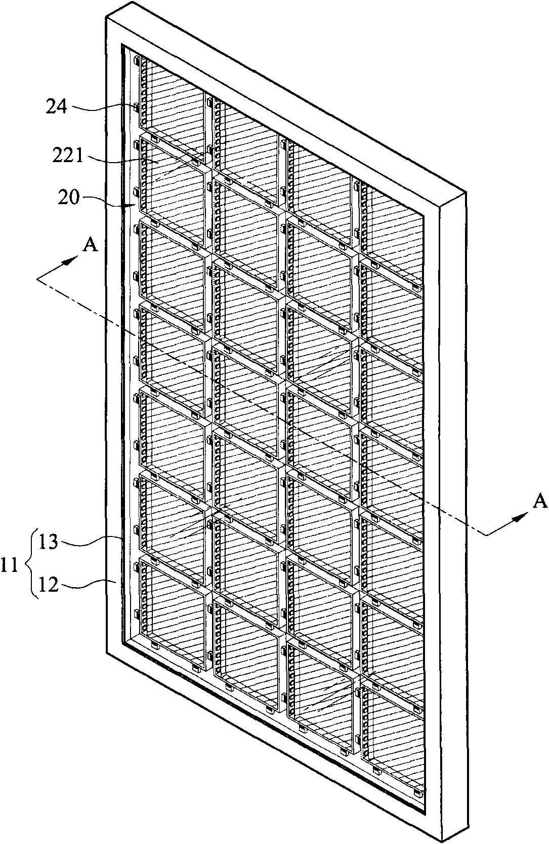
[0055] figure 1 It is a three-dimensional exploded embodiment diagram of a light box structure 10 with a modular light source of the present invention. figure 2 yes figure 1 The ...


PUM


Abstract

The invention relates to a light box structure with a modular light source and a modular light source structure thereof, wherein the light box structure comprises a light box body and a plurality of modular light sources. Each modular light source is fixedly arranged in a frame of the light box body and provided with a shell, a light guide plate, a light-emitting unit and a plurality of electrically connecting parts. The light guide plate is combined with the shell, the light-emitting unit is combined in a light incident surface of the light guide plate in an optical coupling mode and the electrically connecting parts are arranged on at least one side of the shell. Light-emitting units of each modular light source are mutually and electrically connected through the electrically connectingpart, thus light sources with various sizes can be formed and used for various advertisement light boxes and the modular light source structure can replace a light source structure with single size. The invention can reduce the using amount of light emitting diodes, is easy to radiate, reduces the manufacturing cost of the light sources, avoids the stock and can enlarge the application range.

Description

technical field [0001] The invention relates to a light box structure with a modular light source and its modular light source structure, in particular to a light box structure with a modular light source and its modular light source structure used in light box advertisements. Background technique [0002] Generally, the light box structure used in light box advertising is composed of a light-transmitting light box body and a light source. Due to different purposes, such as: promotion, display, advertisement...etc., it must be based on different purposes. Make light box structures of various sizes. However, for light box structures of various sizes, the backlight sources need to be prepared in various sizes, which will increase the cost of material inventory, packaging, storage and transportation. [0003] As disclosed in Taiwan Patent No. M289892, "modular light box and its combination", it has a plurality of modular light boxes; and a control unit. Each modular light box...

Claims


Application Information

Patent Timeline
Patent Type & Authority Applications(China)
IPC IPC(8): F21V15/01F21V21/00F21V8/00F21V23/06G09F13/04F21Y101/02F21Y105/10F21Y115/10
Inventor 李鑫浓
Owner SINOLOGY ENTERPRISE
Learn More