Impeller of wind-air engine and wind-air engine

A technology of engine and impeller, which is applied in the direction of wind power engine, control of wind power engine, engine, etc., can solve the problem of no driving speed, etc., and achieve the effect of shortening the jetting time

Inactive Publication Date: 2010-03-31
丛洋
View PDF3 Cites 1 Cited by
  • Summary
  • Abstract
  • Description
  • Claims
  • Application Information

AI Technical Summary

Problems solved by technology

At present, known engines that convert wind power into mechanical kinetic energy are installed at fixed locations. Since the mechanical device on which the engine is installed has no speed, the engine can only passively accept the wind force limited by the natural weather and environmental conditions. To promote the operation of its impeller to generate mechanical kinetic energy, no engine has been found that can actively convert the wind resistance airflow encountered by a power machine with a certain driving speed into mechanical power.

Method used


Image

  • Impeller of wind-air engine and wind-air engine
  • Impeller of wind-air engine and wind-air engine
  • Impeller of wind-air engine and wind-air engine

Examples


Embodiment Construction

[0041] The present invention will be further described in detail below in conjunction with the accompanying drawings and specific embodiments.

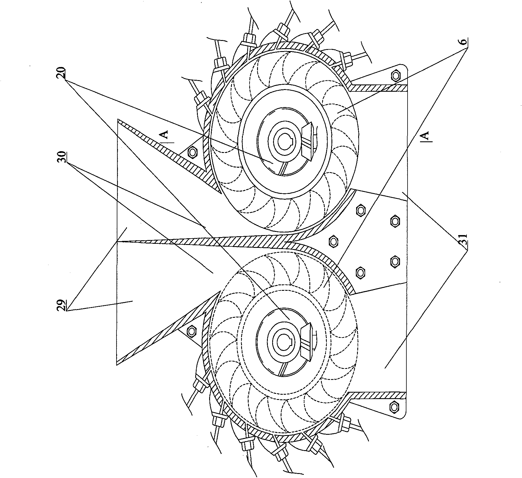
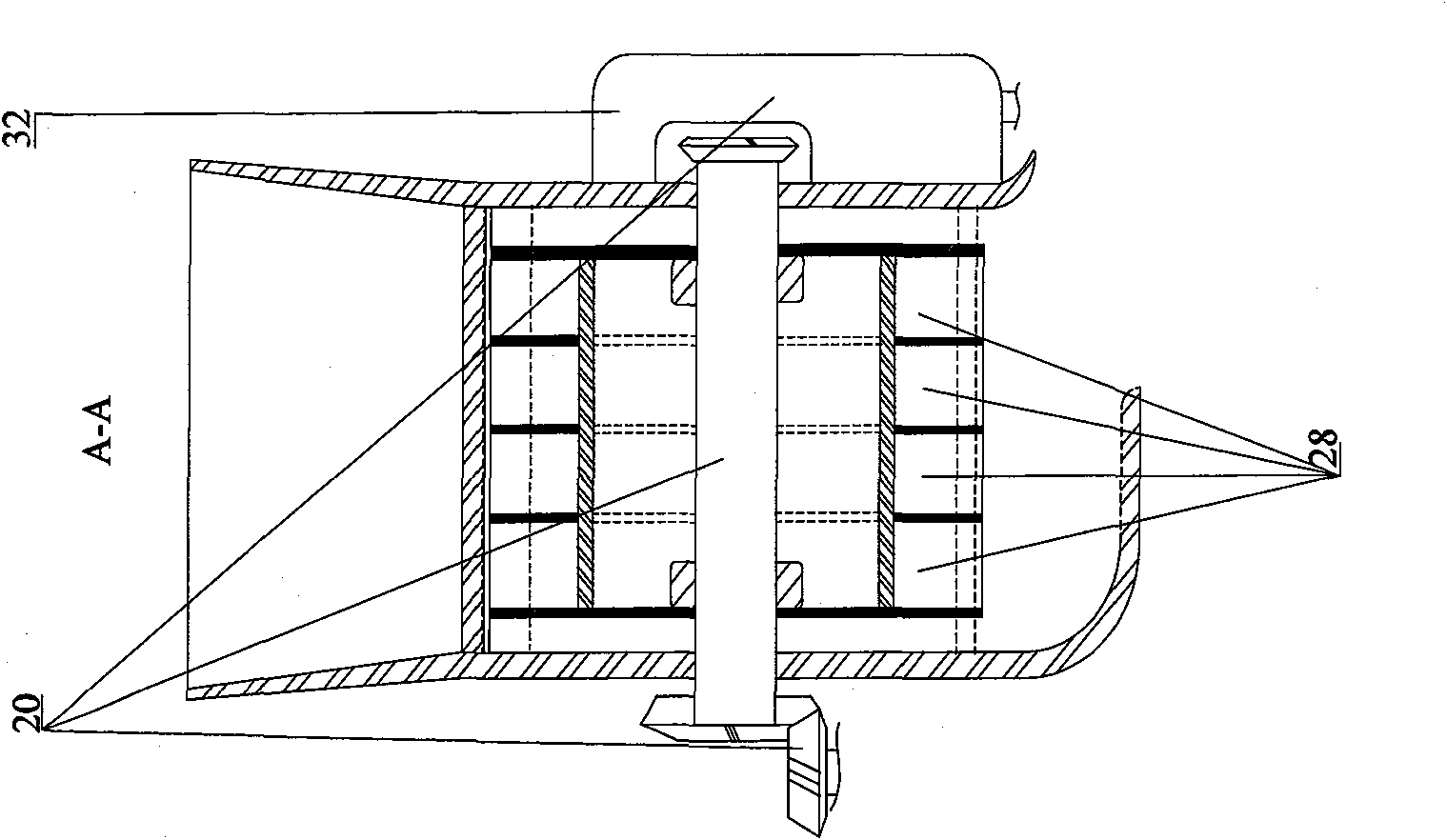
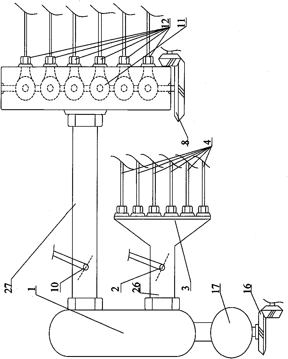
[0042] In the figure, wind engine is made up of following mechanism and system: wind engine 20 is made up of the outer port 29 of directional cylindrical air inlet, the inner mouth 30 of directional cylindrical air inlet, impeller chamber 28, impeller 6, impeller flywheel 14. The left impeller main shaft auxiliary power bevel gear 7, the right impeller main shaft auxiliary power bevel gear 15, the central main power output gearbox 32 and the air outlet 31 and other mechanisms; the wind engine high-pressure gas regeneration reserve supply system includes: storage Gas tank 1, high-pressure air compressor 17, transmission bevel gear 16 connected to high-pressure air compressor, etc.; wind engine starting acceleration jet system, including: central controllable high-pressure gas starting accelerator 2, distributor 3, connecting distributor...


PUM


Abstract

The invention discloses an impeller of a wind-air engine, which comprises an impeller (6) provided with a plurality of impeller chambers (28). The invention also discloses a wind-air engine, which comprises the impeller (6) provided with the plurality of impeller chambers (28); and a shell provided with the impeller is provided with an air inlet for receiving wind resistance airflow, a nozzle usedfor spraying high pressure air into the impeller chambers (28) and an air outlet. The invention further discloses a motor vehicle provided with the wind-air engine. The high pressure air is used as power, so no fuel consumption, exhaust gas or hot air emission exists. The external wind resistance airflow is received to drive the impeller to generate auxiliary power, and the external resistance airflow met by the motor vehicle in running is skillfully converted into power and utilized, so the energy consumption can be greatly reduced and the running speed of a power machine can be greatly improved.

Description

[0001] The present invention is a divisional application of an international application whose application number is 2005800442186 (PCT / CN2005 / 001911), the application date is November 14, 2005, and the title of the invention is: wind engine, that is, an engine that uses wind pressure to replace fuel energy. technical field [0002] The invention relates to an engine, which is installed on all power machines with running speed such as large, medium and small passenger and cargo cars, railway trains, subway trains, ship power, aviation power, etc. with steering wheels on land, and belongs to the field of machinery. Background technique [0003] The engine that uses fuel as energy needs to consume a large amount of fuel, and discharges a large amount of exhaust gas and hot gas, polluting the environment. In order to save fuel energy and protect the earth's environment, human beings are more eager for an engine that does not require fuel consumption, eliminates exhaust gas, hot ...

Claims


Application Information

Patent Timeline
Patent Type & Authority Applications(China)
IPC IPC(8): F03D9/00F03D3/06F03D3/04B60K16/00F03B1/00F03D3/00F03D7/06F03D9/17
CPCF03D3/005Y02E60/15B60K2016/006Y02T10/90F05B2240/215F03D9/028B60L8/006Y02T10/7083Y02E70/30Y02E10/72F05B2240/941B60K16/00F03D3/02Y02E10/74F03B17/00F05B2240/217Y02E10/20Y02E10/728F03D9/12F03D9/17B60L2200/26Y02E60/16F03D9/28F03D9/32F03D3/0463Y02T90/16Y02T10/7072B60T1/10
Inventor 丛洋
Owner 丛洋
Why Eureka
Try Eureka