
Industrial robot

A technology of industrial robots and motors, applied in the direction of manipulators, manufacturing tools, program-controlled manipulators, etc., can solve problems such as inability to properly correct deflection

Active Publication Date: 2010-03-31
SANKYO SEIKI MFG CO LTD
View PDF7 Cites 12 Cited by
  • Summary
  • Abstract
  • Description
  • Claims
  • Application Information

AI Technical Summary

Problems solved by technology

Therefore, when the weight of the workpiece placed on the hand fluctuates, it may not be possible to properly correct the deflection of the hand, etc.

Method used


Image

  • Industrial robot
  • Industrial robot
  • Industrial robot

Examples


other Embodiment approach

[0096] The above-described embodiment is an example of a more preferable embodiment of the present invention, but the present invention is not limited thereto, and various modifications can be made without changing the gist of the present invention.

[0097] In the above-described embodiment, the inclination correction motor 37 and the eccentric shaft 39 are mounted on the supporting member 7, the mounting member 41 is fixed on the bottom surface of the frame 27 of the linear drive unit 4, and the fulcrum portion 36 is formed between the linear drive unit 4 and the supporting member. 7 connections. In addition to this, for example, a structure may be adopted in which the inclination correction motor 37 and the eccentric shaft 39 are mounted on the linear drive unit 4, the mounting member 41 is fixed to the bottom surface of the hand 3, and the fulcrum portion 36 is formed on the linear drive unit. 4 and the link between the hand 3.

[0098] In the above-described embodiment, ...


PUM


Abstract

The invention provides an industrial robot, even if the weight of the conveyed object article is changed, incline of the conveyed object article loaded on hand can be appropriately corrected. The industrial robot includes: hands for loading conveyed object articles; an incline correcting mechanism for correcting incline of the conveyed object article induced by the bending flexure of hand when loading a conveyed object article. The incline correcting mechanism includes: a motor used as a driving source for correcting incline, a eccentrically-pivoted moving component linked with the output shaft of the motor for correcting incline, a linkage rod component installed above the eccentrically-pivoted moving component at the lower end side, and an installation component installed at the upper end side of the linkage rod component. The incline correcting mechanism uses an installation component which moves up and down along with the rotation of the eccentrically-pivoted moving component and the linkage rod component, thereby the hand rotates towards the direction of incline variation of the conveyed object article using the suspension centre section as a rotation center.

Description

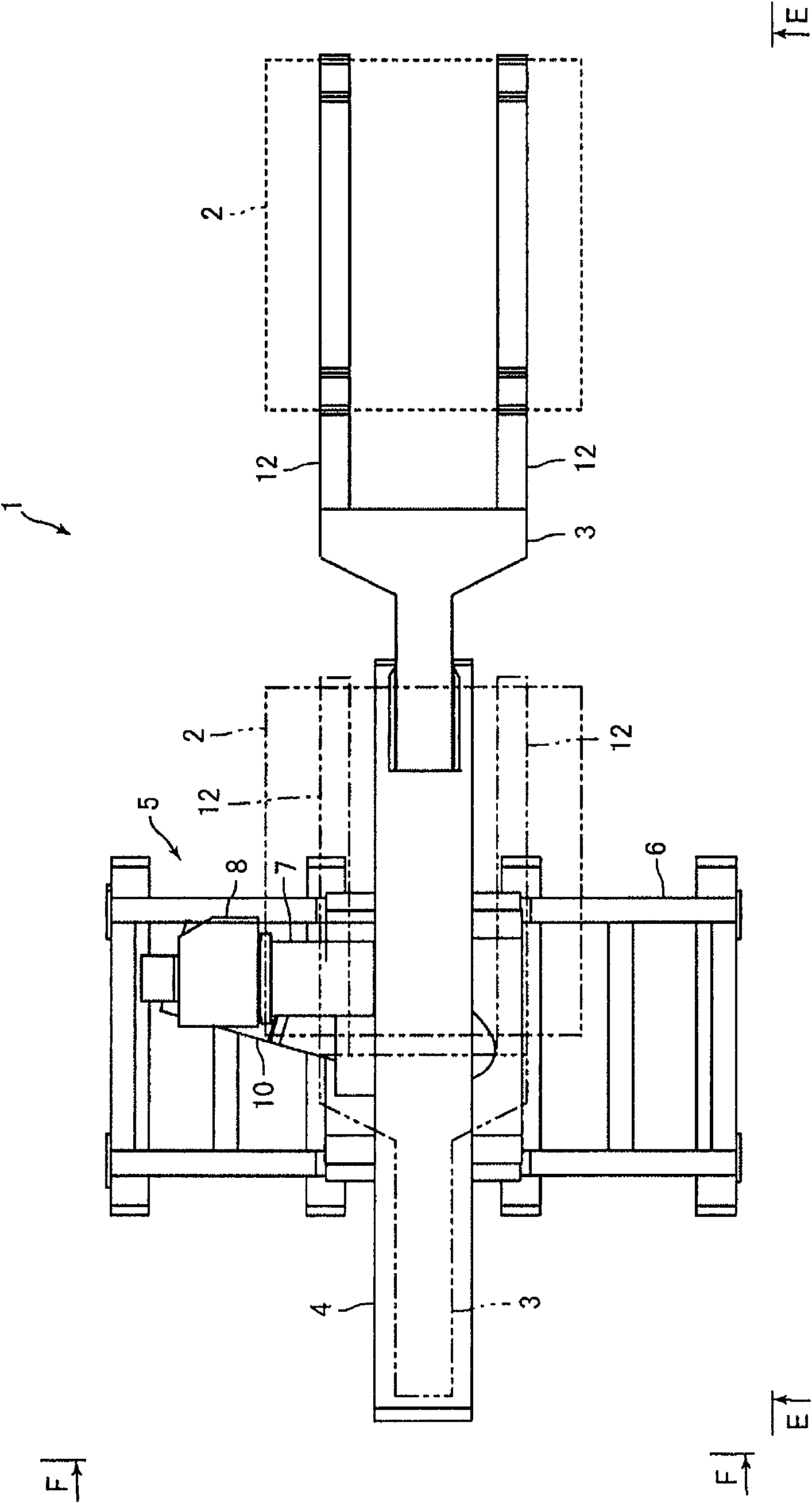
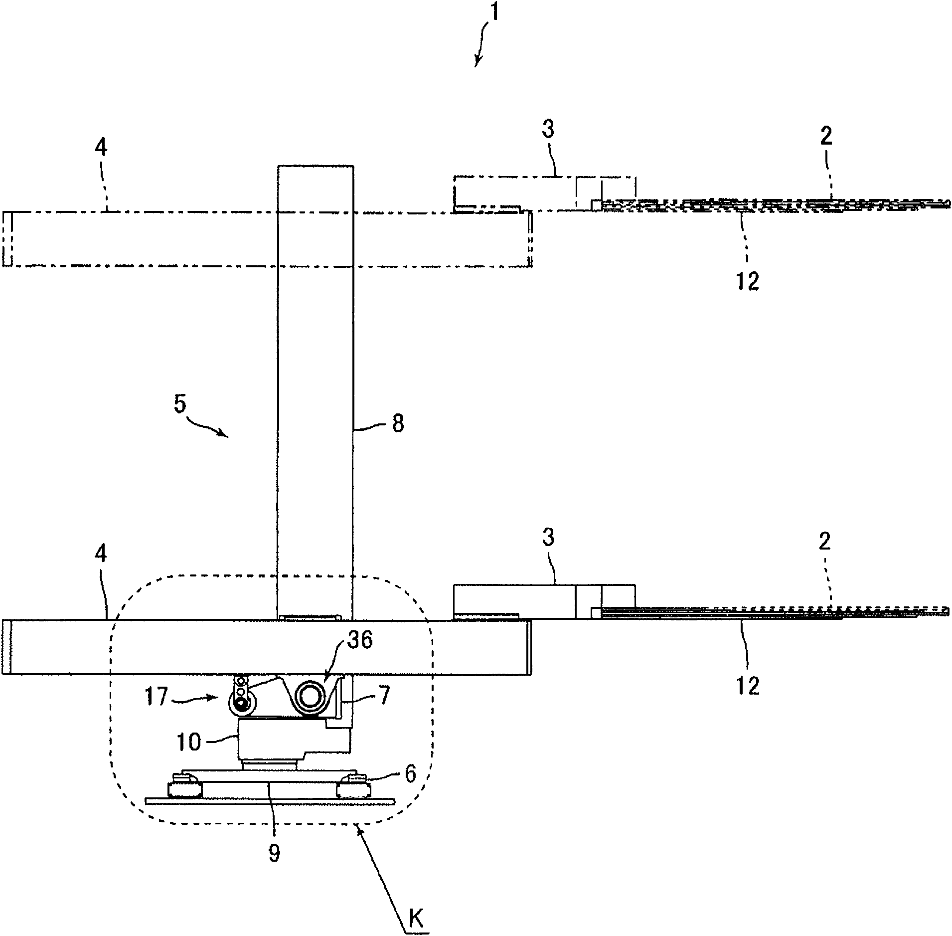
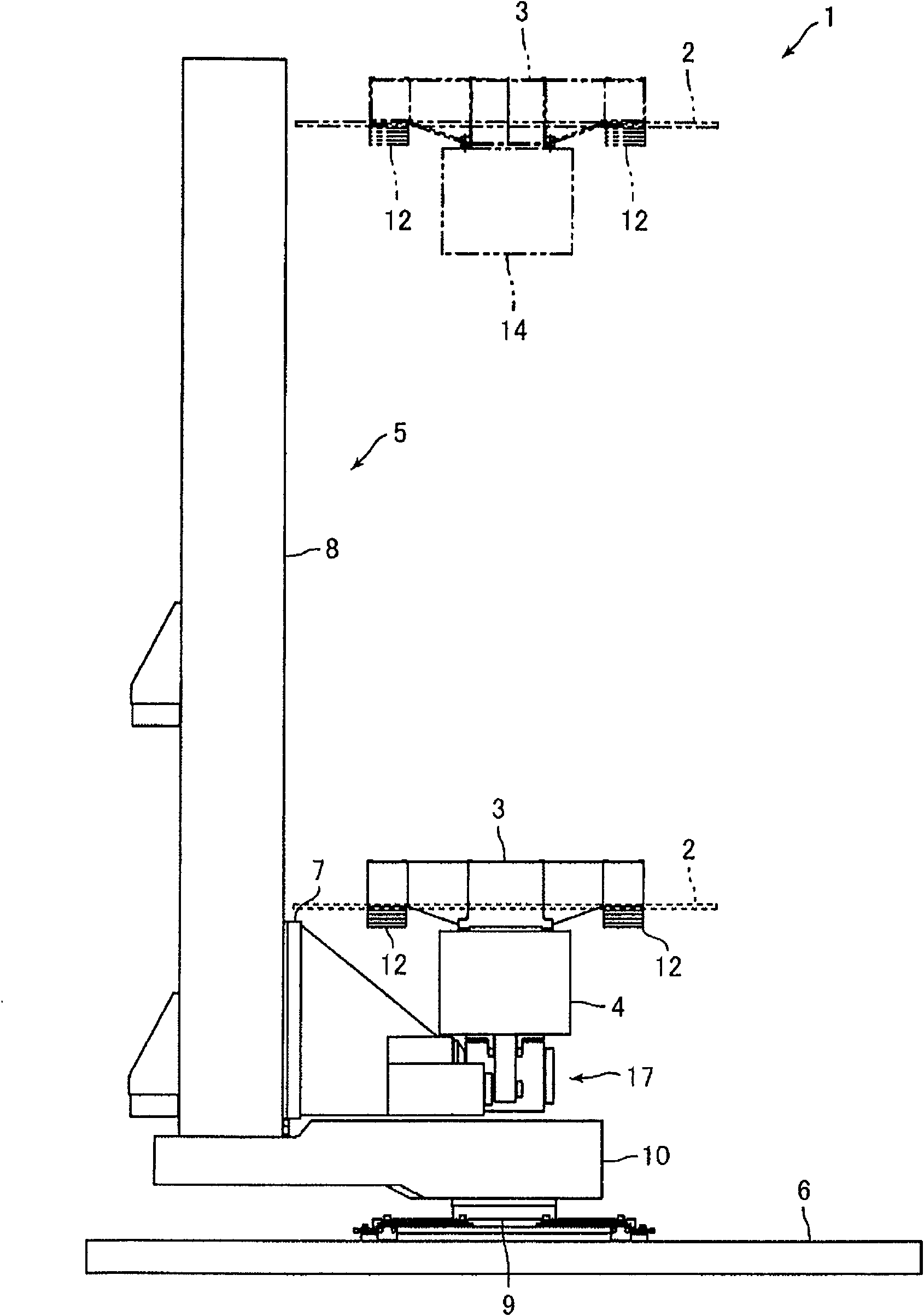
technical field [0001] The present invention relates to an industrial robot that transports a predetermined object to be transported. Background technique [0002] Conventionally, industrial robots that transport predetermined objects (workpieces) have been widely used. As such an industrial robot, an industrial robot including a hand for loading a workpiece and two arms is known (for example, refer to Patent Document 1). In the industrial robot described in Patent Document 1, the proximal end side of the hand is connected to the distal end side of the first arm, and the proximal end side of the first arm is connected to the distal end side of the second arm. [0003] In the industrial robot described in Patent Document 1, a deflection correction mechanism for correcting deflection of the hand, first arm, and second arm when a workpiece is loaded on the hand is provided at the connection between the hand and the first arm. parts. The above-mentioned deflection correction ...

Claims


Application Information

Patent Timeline
Patent Type & Authority Applications(China)
IPC IPC(8): B25J9/00B25J19/00B25J13/00
CPCB25J9/126B25J9/1692B25J15/0014
Inventor 矢泽隆之佐藤史朗增泽佳久
Owner SANKYO SEIKI MFG CO LTD
Learn More