Accumulator, and method for the production of an accumulator

A storage battery and lead storage battery technology, applied in the direction of lead-acid battery, lead-acid battery construction, secondary battery, etc., can solve the problems of high manufacturing cost, etc., achieve low material consumption, simple modification, and improve the effect of seismic strength

Inactive Publication Date: 2010-03-24
VB AUTOBATTERIE GMBH
View PDF1 Cites 0 Cited by
  • Summary
  • Abstract
  • Description
  • Claims
  • Application Information

AI Technical Summary

Problems solved by technology

High precision requirements for plate stacks and housings lead to high manufacturing costs

Method used


Image

  • Accumulator, and method for the production of an accumulator
  • Accumulator, and method for the production of an accumulator

Examples


Embodiment Construction

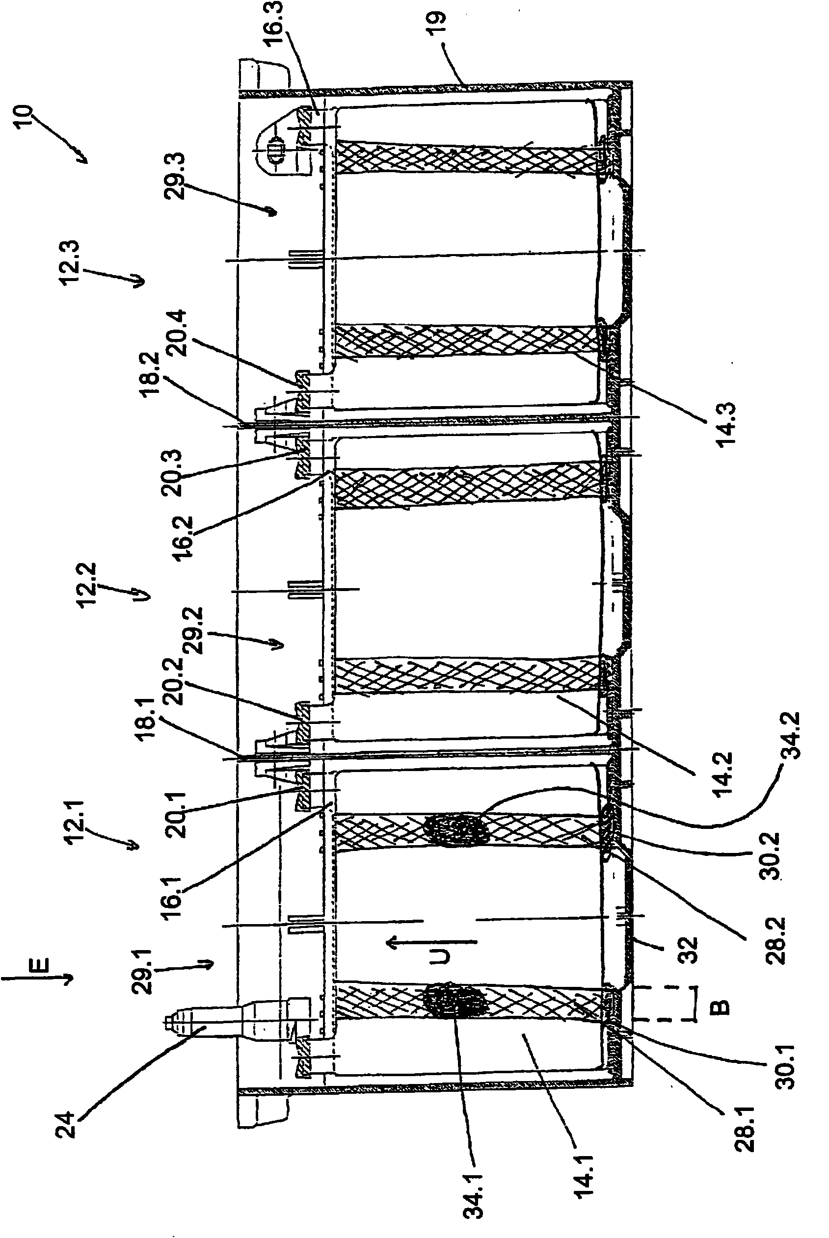
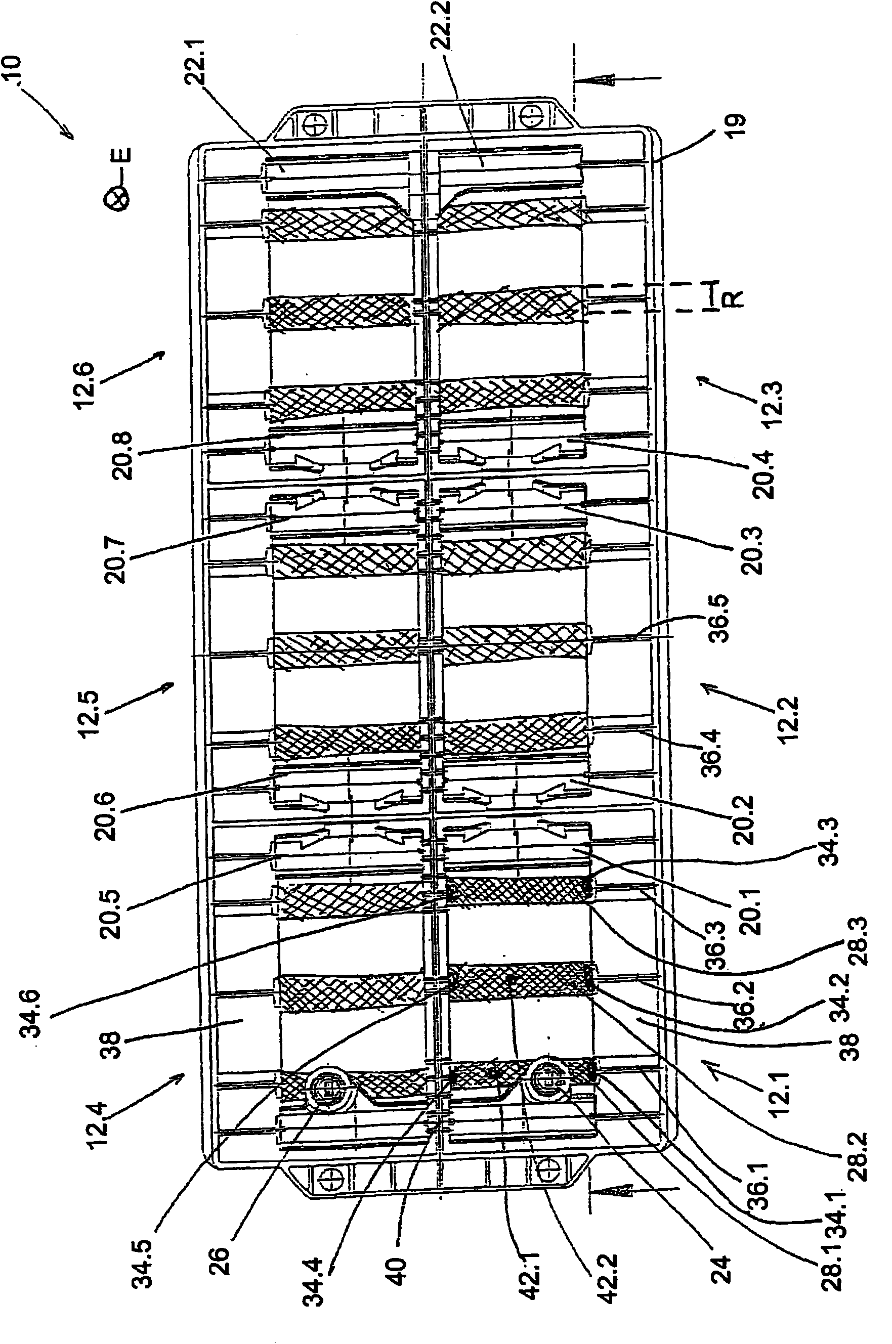
[0018] figure 1 A battery is shown in transverse section. The accumulator comprises primary cells 12.1 to 12.6, wherein, in figure 1 Galvanic cells 12.1, 12.2 and 12.3 are shown in . Galvanic cells 12.1, 12.2 and 12.3 each comprise a plurality of plates 14.1 and 14.2 and 14.3 spaced apart from one another forming a positive plate set and negative plates 16.1 and 16.2 and 16.3 forming a negative plate set. The primary cells 12.1 to 12.3 are separated spatially and electrically by separators 18.1, 18.2 and are arranged in a housing 19. In the following, reference numerals with numerical suffixes ".1", ".2", . . . denote corresponding concrete objects. Reference numerals without a numerical suffix refer to general objects.

[0019] The positive and negative plates are mechanically and electrically connected separately to connectors 20.1, 20.2, 20.3 and 20.4, respectively. The respective two connectors 20.1 and 20.2 and 20.3 and 20.4 are mechanically and electrically connecte...


PUM


Abstract

The invention relates to an accumulator (10), particularly a prismatic lead accumulator, comprising a housing and (a) at least one stack (29) of plates, (b) which has a plurality of spaced-apart poleplates (14, 16) that are entirely surrounded by a fixing element (28) in at least one circumferential direction (U). According to the invention, the fixing element (28) is fixedly connected to the housing (19).

Description

technical field [0001] The invention relates to an accumulator, in particular a prismatic lead accumulator, having a housing and at least one plate stack arranged in the housing, wherein the plate stack has a plurality of pole plates spaced apart from each other, the poles The plate is completely surrounded by the fastening element at least in one circumferential direction. According to a second aspect of the invention, the invention also relates to a method for producing an accumulator. Background technique [0002] A battery of this type is known, for example, from DE 20 2006 001 509 U1. In said document, fixing elements in the form of thermoplastically welded strips are used in order to fix together the plates of the plate stack. A significant advantage of this arrangement is that the housing of the accumulator can be provided with a low wall thickness, since no pressure must be applied to the plate stack to ensure sufficient shock resistance of the accumulator. Howeve...

Claims


Application Information

Patent Timeline
Patent Type & Authority Applications(China)
IPC IPC(8): H01M10/14H01M10/16
CPCH01M2/1072H01M10/16Y02E60/126H01M10/128Y10T29/49114Y10T29/49108Y02P70/50Y02E60/10
Inventor O·博施
Owner VB AUTOBATTERIE GMBH
Why Eureka
Try Eureka