Leak stoppage structure of diaphragm pump head cover body

A head cover body and diaphragm pump technology, which is applied to the components, pumps, and pump components of pumping devices for elastic fluids, can solve problems such as loss of product reputation, increase in manufacturing and maintenance costs, and thinning of thickness.

Active Publication Date: 2010-03-24
蔡应麟 +1
View PDF11 Cites 15 Cited by
  • Summary
  • Abstract
  • Description
  • Claims
  • Application Information

AI Technical Summary

Problems solved by technology

[0011] In order to improve the above-mentioned "leakage water loss", some diaphragm pump manufacturers have introduced improved designs for anti-leakage, such as Figure 11 and Figure 12 As shown, the height of the outer convex strip 22a in the diaphragm 20 is increased, and at the same time, the original stepped groove of the pump head cover 50 is changed into a single groove 56, wherein the outer surface 224 of the outer convex strip 22a The height is approximately equal to the height of the upright wall surface 562 of the groove 56, so that after the diaphragm 20, the piston valve body 40 and the water-stop gasket 60 are nested and combined, and then placed on the groove 56 abutting against the pump head cover 50, The top surface 223 of the outer convex strip 22a of the diaphragm 20 and the top surface 61 of the water-stop gasket 60 just form the same height and are aligned, and at the same time, it is closely attached to the horizontal bottom surface 561 of the groove 56, while the outer convex strip 22a Side 224 then just in time and the upright wall surface 562 of this groove 56 completely lean against each other (as Figure 12 as shown in the partial enlarged view); it was originally thought that the above-mentioned improved design method would improve or eliminate the "leakage water loss", but the occurrence of the "leakage water loss" could not be avoided after the actual test. Water-stop gasket 60 can cause thickness thinning after being bumped for a period of time, still can produce gap G between its top surface 61 and the horizontal bottom surface 561 of groove 56 (as Figure 13 shown), so the tap water W accompanied by the water hammer pressure Wg will also seep into the gap G immediately after entering the water inlet 52 of the pump head cover 50 (such as Figure 13 shown), and finally through the gap δ between the outer surface 224 of the outer convex strip 22a and the upright wall surface 562 of the groove 56, directly leak out of the diaphragm pump from between the pump head cover 50 and the upper cover seat 11
[0012] Therefore, the above-mentioned "leakage loss" will not occur immediately when the new product is first used, but if the user lives in a tropical or cold zone, the effect of thermal expansion and contraction of the climate is more significant, the water-stop gasket The aging phenomenon of the 60% material will intensify, so that it often occurs before the warranty period of the diaphragm pump is reached, so that all manufacturers of diaphragm pumps are forced to replace new products to fulfill the warranty responsibility, which will not only cause their own product reputation in the long run In addition, it will increase the overall manufacturing and maintenance costs, so how to effectively and simply solve the "leakage loss" has become an urgent and important issue

Method used


Image

  • Leak stoppage structure of diaphragm pump head cover body
  • Leak stoppage structure of diaphragm pump head cover body
  • Leak stoppage structure of diaphragm pump head cover body

Examples


Embodiment Construction

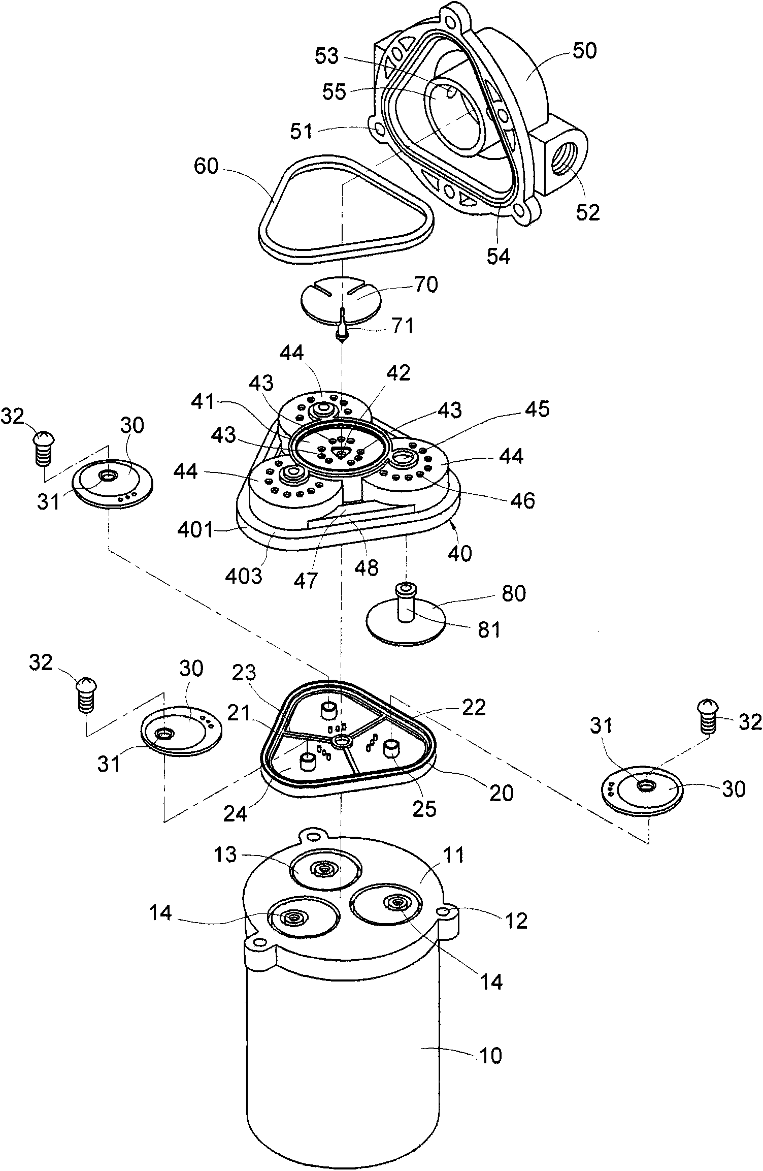
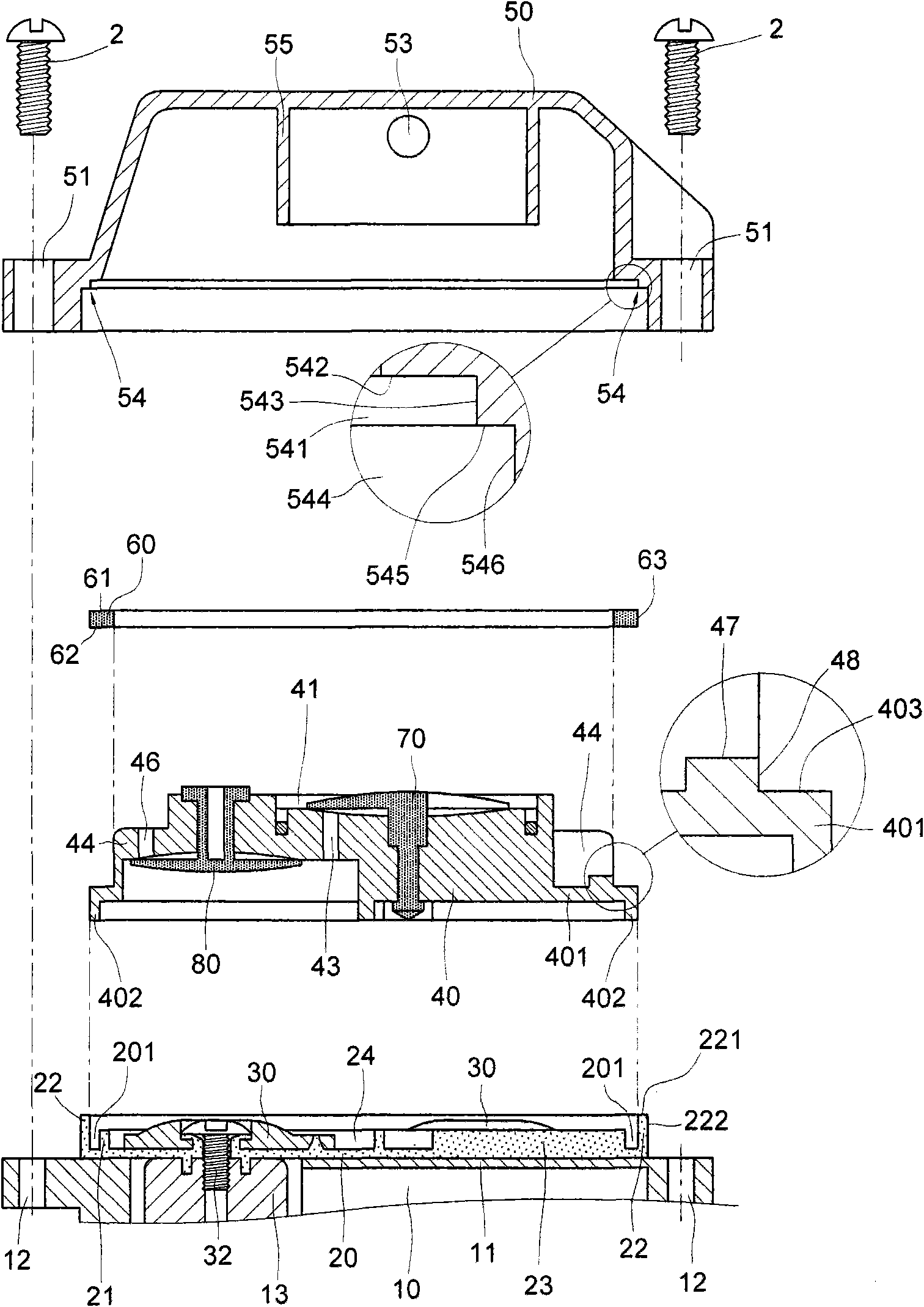
[0079] like Figures 14 to 16 As shown, it is the first embodiment of the leak-proof structure of the pump head cover of the diaphragm pump according to the present invention. Wall 547 (eg Figure 12 ), so that after the water-stop washer 60 is threaded and positioned on the edge top surface 403 of the base 401 of the piston valve body 40, it is tightly plugged into the stepped groove 54 of the pump head cover 50. (like Figure 15 shown), the outer side surface 63 of the water-stop washer 60 will be contacted and squeezed by the inclined wall surface 547 in the lower step groove 541 in the stepped groove 54, and a horizontal level will be generated on the outer side 63 of the water-stop washer 60 immediately. The force Fh (such as Figure 16 In this case, under the blocking action of the outer edge surface 48 of the positioning protruding strip 47 in the piston valve body 40, the water-stop washer 60 will be vertically squeezed and deformed, and the Its interior will synch...


PUM


Abstract

The invention provides a leak stoppage structure of a diaphragm pump head cover body, which sets the vertical wall surface of a lower step tank in an opening step tank at the bottom part of the pump head cover body into an inclined wall surface, so as to ensure that a horizontal acting force is generated on the outer surface of a water stoppage gasket immediately when the outer surface of the water stoppage gasket is contacted and pressed by the inclined wall surface in the lower step tank; and the water stoppage gasket generates vertical pressing and deformation under the blocking function ofthe outer edge surface of a fixed raised line in a piston valve body, thus achieving the effect of blocking the high pressure water to leak to the outside of the diaphragm pump.

Description

(1) Technical field: [0001] The invention relates to a leak-stopping structure for a pump head cover of a diaphragm pump. The water pressure inside the pump head cover leaks into the leak-proof structure of the motor. The invention completely solves the phenomenon of water leakage caused by instantaneous water hammer pressure caused by the gravitational potential energy accompanying the height drop of the tap water in the pump head cover of the existing diaphragm pump. (2) Background technology: [0002] Diaphragm booster pumps for reverse osmosis water filters are currently known, and have been disclosed such as US Pat. , 6604909, 6840745, 6892624, 7083392, and Taiwan Invention Patent Case No. 095122820, etc. Among them, the Taiwan Invention Patent Case No. 095122820 was applied for by the applicant in this case on June 23, 2006 and has been approved in The case has not yet been announced, and its structure is as follows Figure 1 to Figure 6 As shown, it includes: a moto...

Claims


Application Information

Patent Timeline
Patent Type & Authority Applications(China)
IPC IPC(8): F04B53/16F04B43/04F04B53/00
Inventor 徐兆火蔡应麟
Owner 蔡应麟
Why Eureka
Try Eureka