
Device and method for implementing rotation of screen image

A technology of screen image and implementation method, applied in the field of display screen, to achieve the effect of automatic rotation

Inactive Publication Date: 2010-03-17
YINGHUADA (SHANGHAI) ELECTRONIC CO LTD
View PDF6 Cites 22 Cited by
  • Summary
  • Abstract
  • Description
  • Claims
  • Application Information

AI Technical Summary

Problems solved by technology

[0005] In view of this, the present invention provides a device and method for realizing screen image rotation, so as to solve the problem in the prior art that the screen image rotation needs to be realized by manually setting or rotating the electronic device

Method used


Image

  • Device and method for implementing rotation of screen image
  • Device and method for implementing rotation of screen image
  • Device and method for implementing rotation of screen image

Examples


Embodiment 1

[0054] Embodiment 1. In this embodiment, the judgment point is located on a plane, and the gravity recognition device is always located on the plane.

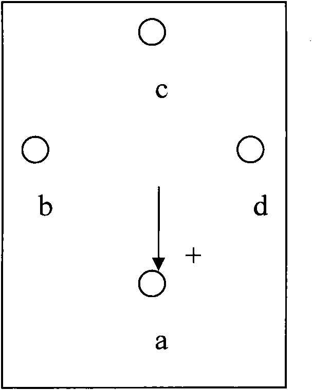
[0055] The judgment point of the position recognition unit can be arbitrarily selected on a circle with the length of the gravity hammer as the radius on the plane. In this embodiment, only 4 judgment points a, b, c, d is an example for description.

[0056] Please refer to image 3 , Is a schematic diagram showing the position of the gravity hammer. a, b, c, d represent the judgment points of the position of the gravity hammer, image 3 In the middle, "+" means that a high level is applied to the gravity hammer, and a low level is applied to the four points a, b, c, and d. image 3 The middle arrow indicates that the gravity hammer is located at point a and touches point a. Then point a is triggered, and point a changes from low to high. Similarly, if the gravity hammer is at point b and touches point b, point b is triggered and ...

Embodiment 2

[0062] Second embodiment, in this embodiment, the judgment point is located on a spherical surface composed of space with a certain radius, and the spherical surface is fixed, and the gravity hammer can rotate freely inside the spherical body composed of spherical surfaces.

[0063] This embodiment may have multiple judgment points, for example, the judgment points may be uniformly distributed on the spherical surface. In addition, four reference judgment points a1, b1, c1, d1 are preset, and the plane formed by the reference judgment points is parallel to the mobile phone screen, and the angle of the screen to be rotated is calculated according to the reference judgment points.

[0064] No matter how the phone rotates, the gravity hammer can touch a judgment point m on the sphere. The level of the m point changes from low level to high level. When the m point changes to high level, the m point triggers an interrupt to the CPU. Notify the CPU that the gravity hammer is currently at...


PUM


Abstract

The invention discloses a device and a method for implementing the rotation of a screen image. The device comprises a gravity identification device for identifying gravity, a position identification unit and a screen image rotation unit, wherein the position identification unit is used for identifying the position of the gravity identification device when the gravity identification device triggersa judge point of the position identification unit, and comprises at least one judge point; and the screen image rotation unit is used for executing the rotation of the screen image according to the position of the gravity identification device identified by the position identification unit. The method comprises the following steps that: the gravity identification device identifies the gravity; when the gravity identification device triggers the judge point of the position identification unit, the judge point identifies the position of the gravity identification device; the position identification unit comprises at least one judge point; and the screen image rotation unit executes the rotation of the screen image according to the position of the gravity identification device identified bythe position identification unit. The device and the method realize the automatic rotation of the screen image.

Description

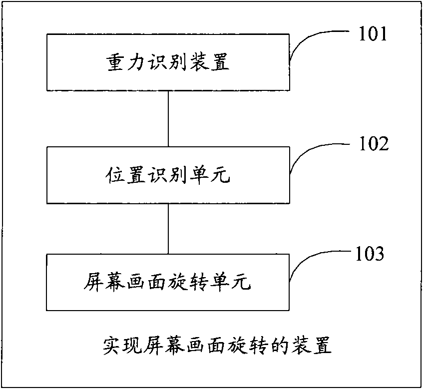
Technical field [0001] The present invention relates to the technical field of display screens, in particular to a device and method for realizing screen rotation. Background technique [0002] At present, electronic devices (such as large-screen smart phones) generally have the function of screen rotation. Users can set the display mode of the screen according to their needs. For example, select "Horizontal" or "Vertical" in the "Settings" column. After confirming, the screen picture can be adjusted according to the setting. [0003] In addition, when the user takes out the electronic device from the pocket, he may find that the electronic device is taken upside down and needs to be rotated before it can be used normally. Or, when the user is driving, he can only operate the electronic device with one hand. , The same need to rotate electronic equipment. [0004] The above-mentioned disadvantage of rotating the screen picture is that when the screen is required to rotate, it needs...

Claims


Application Information

Patent Timeline
IPC IPC(8): G09G5/42
Inventor 翟助民蔡世光何代水
Owner YINGHUADA (SHANGHAI) ELECTRONIC CO LTD
Learn More