Pseudo-random number generating circuit and generating method of radio frequency identification tag chip

A radio frequency identification tag, pseudo random number technology, applied in the field of radio frequency identification, can solve the problems of unfavorable CMOS integration, high power consumption, complex circuit structure, etc.

Inactive Publication Date: 2010-03-17
BEIJING TONGFANG MICROELECTRONICS
View PDF3 Cites 19 Cited by
  • Summary
  • Abstract
  • Description
  • Claims
  • Application Information

AI Technical Summary

Problems solved by technology

However, the shortcomings of the above-mentioned patented technologies are that the circuit structure is complex, the cost is high, and the power consumption is large, which cannot meet the low power consumption requirements of passive radio frequency identification.
Moreover, some of the above methods use special devices, such as Zener diodes, which are not conducive to CMOS integration.

Method used


Image

  • Pseudo-random number generating circuit and generating method of radio frequency identification tag chip
  • Pseudo-random number generating circuit and generating method of radio frequency identification tag chip
  • Pseudo-random number generating circuit and generating method of radio frequency identification tag chip

Examples


Embodiment 1

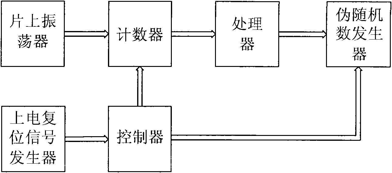
[0054] see figure 1 , the invention includes an on-chip oscillator, a power-on reset signal generator, a counter, a controller, a processor, and a pseudo-random number generator in the radio frequency identification tag chip. The on-chip oscillator, counter, processor and pseudo-random number generator are connected in sequence, the power-on reset signal generator is connected to the pseudo-random number generator through the controller, and the other output of the controller is connected to the counter.

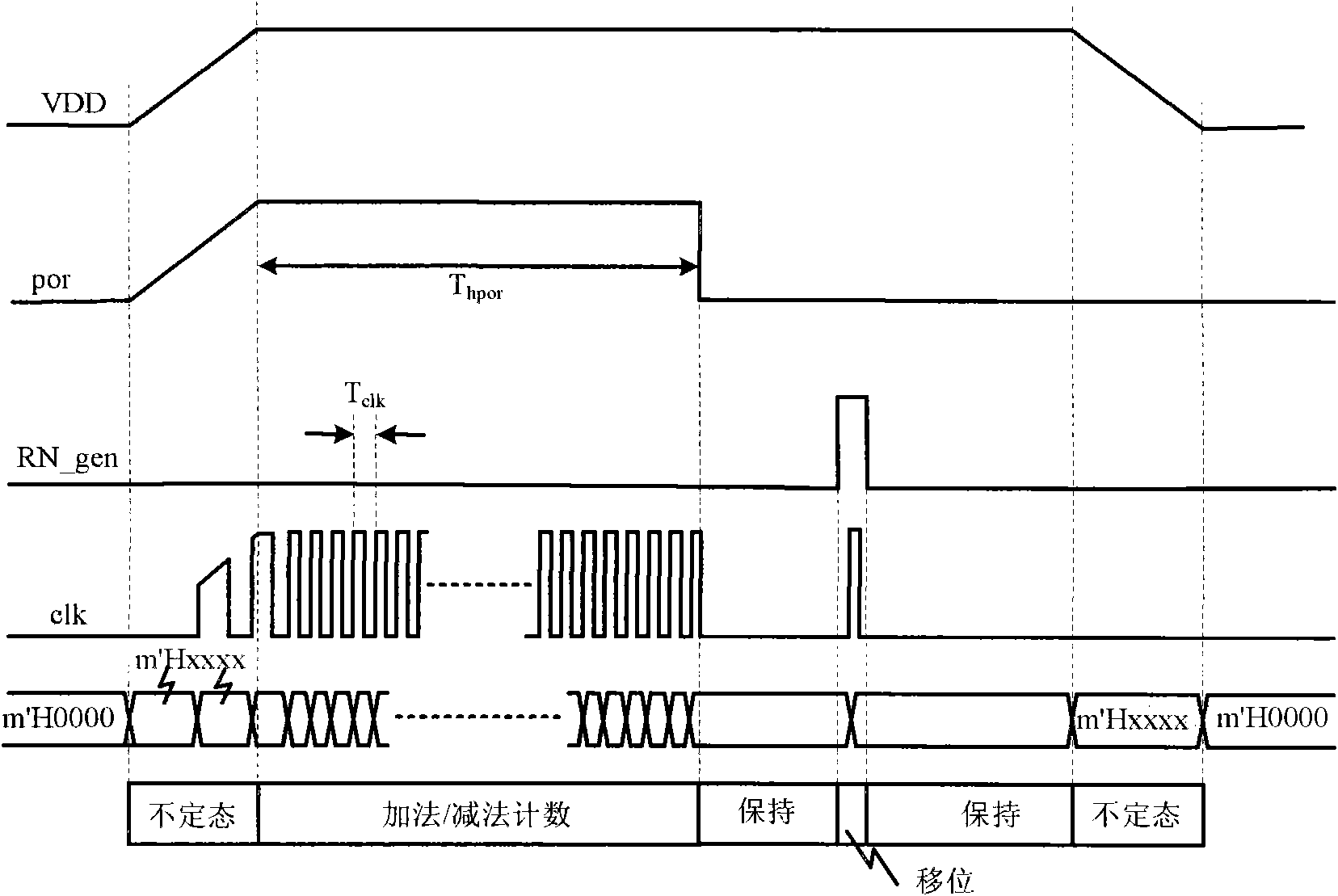
[0055] see figure 2 , the steps of the pseudo-random number generation method of the present invention are:

[0056] ① When the tag chip enters the field area of ​​the card reader, it is powered on, and the power-on reset signal generator generates a power-on reset signal por. for a while T hpor within, the power-on reset signal por is still valid for reset, at T hpor After a certain time, the logic level of the power-on reset signal por is reversed, and the power-on re...

Embodiment 2

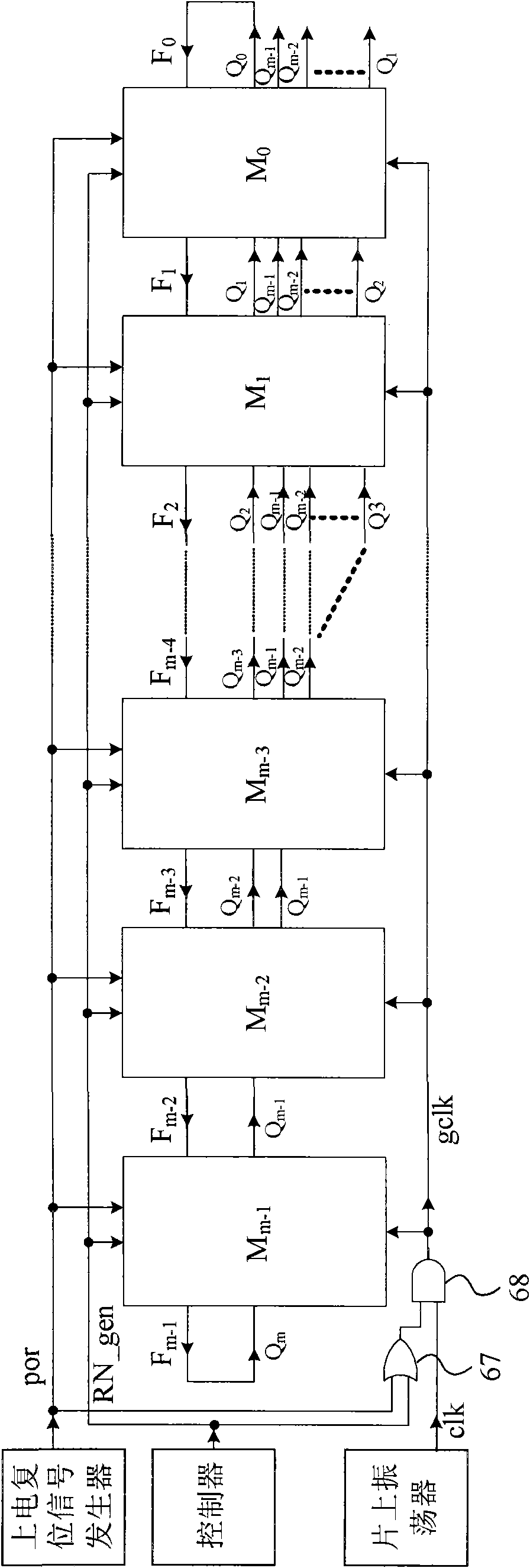
[0062] see Figure 3 to Figure 6, the pseudo-random number generation circuit of the present invention includes an on-chip oscillator in the radio frequency identification tag chip, a power-on reset signal generator, a controller, and a device with three functions of counting, processing the count value to generate a seed, and generating a pseudo-random number Pseudo-random number generator using a sequence of shift registers. The oscillation output of the on-chip oscillator is connected to the clock clk input terminal of the pseudo-random number generator through the gating circuit, and the power-on reset signal output by the power-on reset signal generator is connected to the por input terminal of the pseudo-random number generator. The random number generation enable output signal is connected to the enable terminal RN_gen of the pseudo-random number generator. The gating circuit consists of a two-input AND gate and a two-input OR gate. The output of the power-on reset si...


PUM


Abstract

The invention discloses a pseudo-random number generating circuit and a generating method of a radio frequency identification tag chip, which relate to the radio frequency identification (RFID) technology. The pseudo-random number generating circuit of the invention comprises an on-chip oscillator and a power-on reset signal generator in the radio frequency identification tag chip. The pseudo-random number generating circuit is characterized by also comprising a counter, a controller, a processor and a pseudo-random number generator, wherein the on-chip oscillator, the counter, the processor and the pseudo-random number generator are connected sequentially, the power-on reset signal generator is connected with the pseudo-random number generator through the controller, and the other outputof the controller is connected with the counter. Compared with the prior art, the invention has the characteristics of simple circuit structure, low cost, low power consumption, small area and easy integration.

Description

technical field [0001] The invention relates to radio frequency identification (RFID) technology, in particular to a pseudo-random number generation circuit of a tag chip in the radio frequency identification system and a corresponding pseudo-random number generation method. Background technique [0002] In the field of radio frequency identification technology, there are many methods for anti-collision identification of tags. Some methods, such as pure ALOHA algorithm, random time slot algorithm, etc., need to generate a random number in the tag, and then allocate the time slot of the tag according to the size of the random number. Since the time slot allocation is based on the size of the generated random number, the randomness of the random number directly affects the anti-collision performance of the tag, thereby affecting the identification efficiency of the radio frequency identification system. [0003] In addition to the above-mentioned anti-collision problems in ra...

Claims


Application Information

Patent Timeline
Patent Type & Authority Applications(China)
IPC IPC(8): G06K19/07G06F7/58
Inventor 马长明吴行军
Owner BEIJING TONGFANG MICROELECTRONICS
Why Eureka
Try Eureka