
Radio frequency identification antenna

A radio frequency identification and antenna technology, applied in the directions of antenna supports/installation devices, record carriers used by machines, instruments, etc., can solve the problems of poor use effect, inability to resist metal, pattern and chip matching, etc., and achieve long-distance identification. Effect

Active Publication Date: 2010-03-10
JIAXING GLEAD ELECTRONICS CO LTD
View PDF1 Cites 10 Cited by
  • Summary
  • Abstract
  • Description
  • Claims
  • Application Information

AI Technical Summary

Problems solved by technology

The paper labels currently used are light in weight, but not resistant to metal, and some anti-metal labels do not have a good pattern and chip matching, resulting in poor use effect
There have been no published reports on suitable RFID antennas involving matching problems

Method used


Image

  • Radio frequency identification antenna
  • Radio frequency identification antenna
  • Radio frequency identification antenna

Examples


Embodiment 1

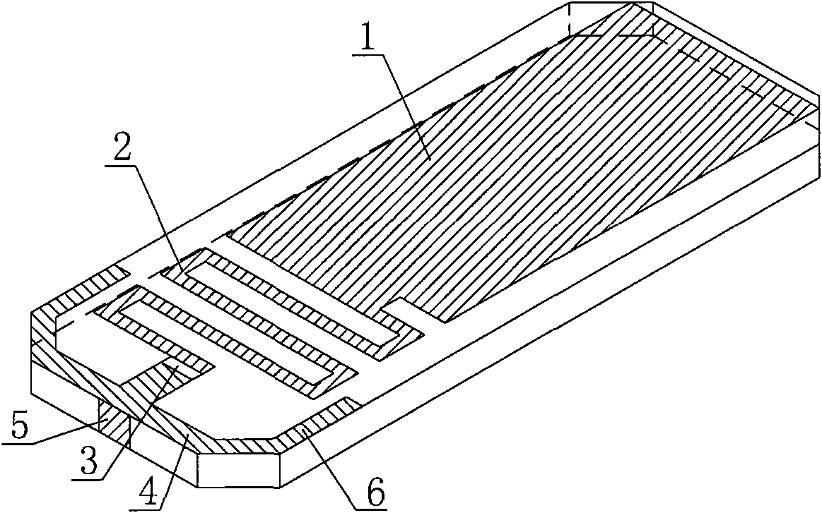
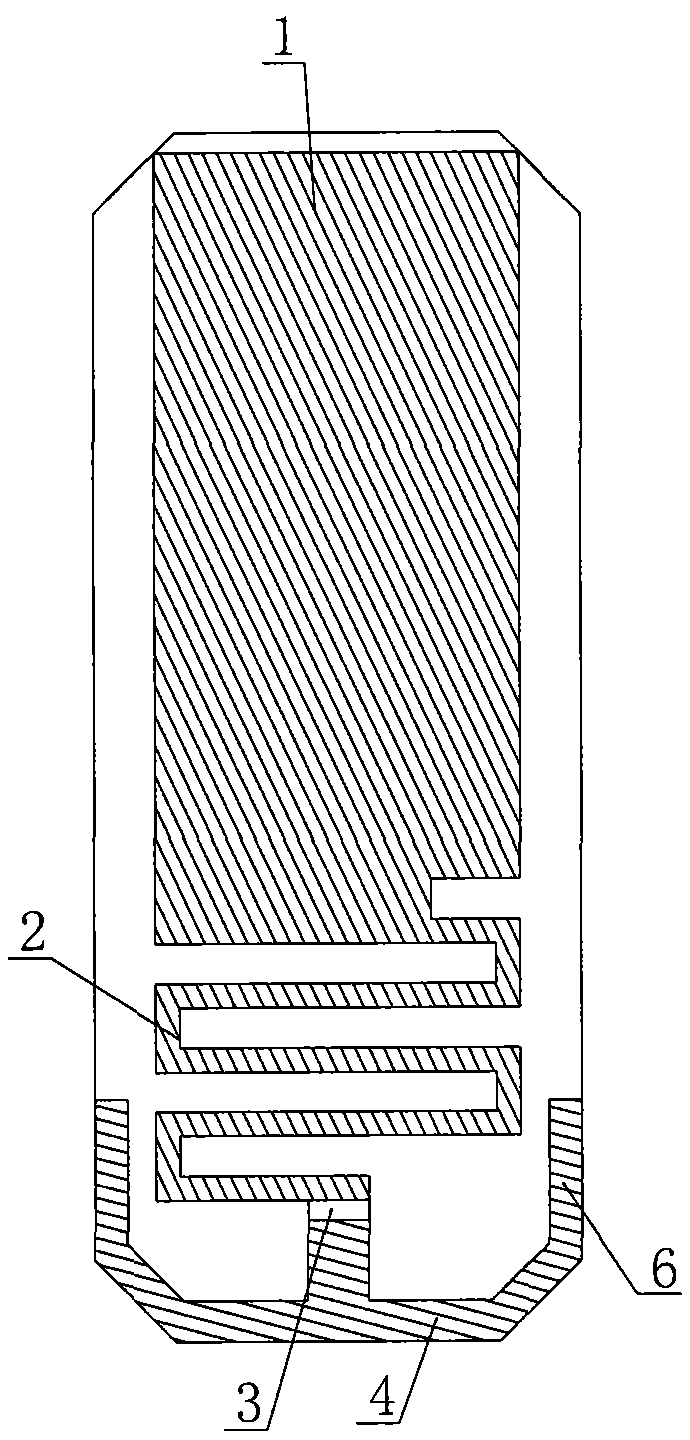
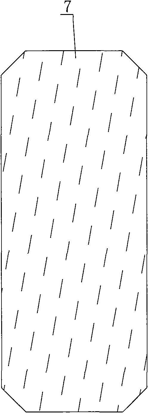
[0022] Such as figure 1 , figure 2 , image 3 A radio frequency identification antenna shown, the radio frequency identification antenna includes a radio frequency tag chip 3, a base body and a metal pattern coated on the base body, the base body adopts a ceramic sheet with a dielectric constant of 5-150, and the metal pattern is composed of a radiation part 1. The feeder matching part 2, the resonant matching part 4, the side connection part 5 and the anti-metal part 7 are composed. The radiation part 1, the feeder matching part 2 and the resonant matching part 4 are on the front of the substrate, and the anti-metal part 7 is on the back of the substrate. Such as figure 2 As shown, the shape of the radiation part 1 is rectangular; the rectangular wave meander line of the feeder matching part 2 is a rectangular wave with 0.115 wavelengths, which can produce inductive matching components of j700~j900. One end of the feeder matching part 2 is connected to the radiation par...

Embodiment 2

[0024] Such as Figure 6 A radio frequency identification antenna shown, the radio frequency identification antenna includes the radio frequency tag chip 3 described in embodiment 1, the substrate and the metal pattern coated on the substrate, the metal pattern consists of the radiation part 1, the feeder matching part 2, the resonance matching part 4. The side connection part 5 and the anti-metal part 7 are composed, the difference is that the shape of the radiation part 1 is octagonal; the rectangular wave meander line of the feeder matching part 2 is a rectangular wave with 0.11 wavelengths, which can produce the inductance of j700~j900 Match components.

Embodiment 3

[0026] Such as Figure 7 A radio frequency identification antenna shown, the radio frequency identification antenna includes the radio frequency tag chip 3 described in embodiment 1, the substrate and the metal pattern coated on the substrate, the metal pattern consists of the radiation part 1, the feeder matching part 2, the resonance matching part 4. The side connection part 5 and the anti-metal part 7 are composed, the difference is that the shape of the radiation part 1 is a polygon; the rectangular wave meander line of the feeder matching part 2 is a rectangular wave with a wavelength of 0.15, which can produce an inductive matching component of j700~j900 . The length of the resonant arm in the resonant matching part 4 becomes almost zero, so that the capacitive matching component is reduced to match the circuit.


PUM


Abstract

The invention relates to an antenna commonly used in a microwave communication system, in particular to an antenna suitable for applying in radio frequency identification. The radio frequency identification antenna comprises a radio frequency tag chip, a basal body and a metal pattern coated on the basal body, wherein the basal body adopts a ceramic chip of which the dielectric constant is 5-150;the metal pattern is composed of a radiation part, a feeder line matching part, a resonance matching part, a side surface connection part and an anti-metal part, wherein the feeder line matching partis a zigzag line, one end is connected with the radiation part, and the other end is connected with the radio frequency tag chip; the resonance matching part is positioned on one end part of the basal body facade, one end is connected with the radio frequency tag chip, and the other end is connected with the side surface connection part; the side surface connection part is positioned on the side surface of the basal body, and the side surface connection part is connected with the anti-metal part. In the invention, the tag antenna matched with the tag chip can achieve 3dBi linear polarization gain and has further identification space if compared with the anti-metal tag with the same size. The antenna of the invention is suitable for frequency range of 800MHz-1GHz.

Description

technical field [0001] The invention relates to an antenna commonly used in a microwave communication system, in particular to an antenna suitable for radio frequency identification applications. Background technique [0002] Radio Frequency Identification (RFID) is a non-contact automatic identification technology. Its basic principle is to use the transmission characteristics of radio frequency signal and space coupling (inductive or electromagnetic coupling) or radar reflection to realize the identification of the identified object. Automatic Identification. The RFID system includes at least two parts: electronic tags and readers. The electronic tag is the data carrier of the radio frequency identification system, and the electronic tag is composed of a tag antenna and a tag-specific chip. According to the different power supply methods of electronic tags, electronic tags can be divided into active electronic tags (Active tag), passive electronic tags (Passive tag) and ...

Claims


Application Information

Patent Timeline
IPC IPC(8): H01Q1/22G06K19/077
Inventor 史纪元葛伟平沈杰高升闫文力占丰富许赛卿
Owner JIAXING GLEAD ELECTRONICS CO LTD
Learn More