
Side cover plate type cable bridge frame

A technology for cable trays and side covers, which is applied in the direction of pipe supports, pipes/pipe joints/fittings, mechanical equipment, etc., which can solve the problems of labor and money, labor and time, and achieve the effect of optimizing the installation structure

Inactive Publication Date: 2010-03-10
ZHENJIANG ZHONGHAO ELECTRIC
View PDF0 Cites 0 Cited by
  • Summary
  • Abstract
  • Description
  • Claims
  • Application Information

AI Technical Summary

Problems solved by technology

Once there is a problem with the cable, all the cover plates must be removed for inspection, which is labor-intensive and time-consuming, costing life and money

Method used


Image

  • Side cover plate type cable bridge frame
  • Side cover plate type cable bridge frame
  • Side cover plate type cable bridge frame

Examples


Embodiment Construction

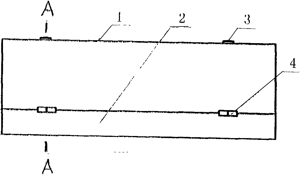
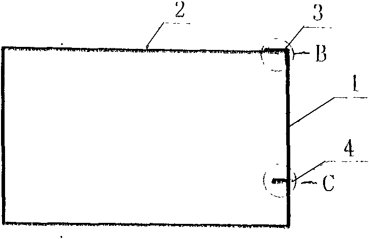
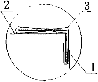
[0016] refer to figure 1 , Fig. 2, the present invention is a kind of side cover plate type cable tray, and this bridge frame is provided with the trough body 2 that section is " G " shape, and a section is set on the notch of trough body and is the side cover plate 1 that section is " U " shape .

[0017] When concretely implementing the present invention, at first the steel plate is folded by the machine "G" shape bridge tank body 2 and "U" shape side cover plate 1, and the upper and lower notches of the tank body 2 are respectively provided with 90° folded inwardly. Degree of strengthening edge. In addition, a commercially available elastic snap lock 3 is provided between the upper side of the side cover and the upper notch of the tank body 2 , and a hinge 4 hinged to each other is provided between the lower side of the side cover 1 and the lower slot of the tank body 2 .

[0018] like Image 6 , during the installation process, the cable tray 5 can be shelved on the sup...


PUM


Abstract

The invention relates to a side cover plate type cable bridge frame which is provided with a groove body with a G-shaped section, and a side cover plate with a U-shaped section is arranged on the notches of the groove body. A 90-degree stiffened edge folded inwards is respectively arranged at an upper notch and a lower notch of the groove body, and a 90-degree stiffened edge folded towards one side is also respectively arranged at the upper edge and the lower edge of the side cover plate. An elastic hasp lock is arranged between the upper edge of the side cover plate and the upper notch of thegroove body, and mutually articulated hinges are arranged between the lower edge of the side cover plate and the lower notch of the groove body. The side cover plate type cable bridge frame can be installed by abutting against the corner top of an object with no need of considering the space of the top surface and the lateral side of the bridge frame, optimizing the installation structure and being quite suitable for the application on various engineering construction and shipping trades. The side cover plate type cable bridge frame can be conveniently, safely, rapidly and reliably installed,and can also be conveniently and rapidly overhauled or dismantled. When cables are laid, only a side cover of the cable bridge frame needs to be laterally opened to easily lay and adjust the cables,and then the side cover plate is covered.

Description

technical field [0001] The invention relates to a bridge used for laying cables in engineering buildings, ships, etc., in particular to a side cover type cable bridge. Background technique [0002] At present, traditional cable trays use a cover plate on the top of the cable trough, and welding damage locks on both sides of the cover plate. Therefore, when installing, when the cable tray must be close to other objects, due to the small space Or narrow, it is really inconvenient to operate, and when the bridge is barely in place, it is difficult to connect. It is very difficult to replace and dismantle. Once there is a problem with the cable, all the cover plates must be removed for inspection, which is labor-intensive and time-consuming, costing life and money. Contents of the invention [0003] The technical problem to be solved by the present invention is to provide a side cover type cable tray with a simple structure and a cover plate on the side of the tank body. ...

Claims


Application Information

Patent Timeline
Patent Type & Authority Applications(China)
IPC IPC(8): F16L3/23
Inventor 任本财任峻平
Owner ZHENJIANG ZHONGHAO ELECTRIC
Learn More