
System and method for compensating maximum output power of switching power supply

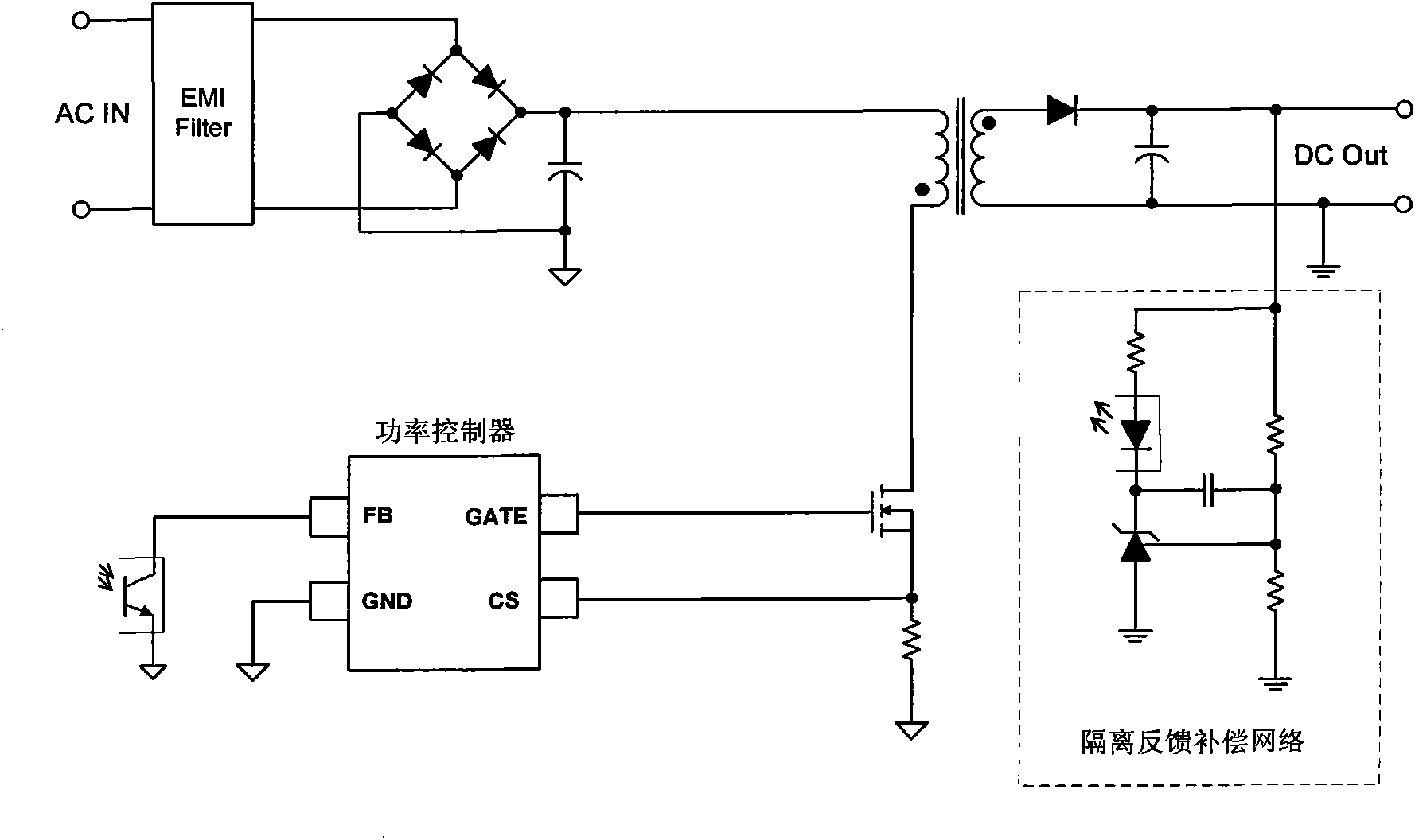
A technology of maximum output power and switching power supply, applied in the direction of output power conversion device, AC power input conversion to DC power output, electrical components, etc., can solve the phenomenon of OPP recovery gap increase, deterioration of sub-harmonic oscillation and large and small waves , system startup failure and other problems, to achieve the effect of overcoming periodic OCP compensation

Inactive Publication Date: 2010-03-03
杨媛媛
View PDF0 Cites 62 Cited by
  • Summary
  • Abstract
  • Description
  • Claims
  • Application Information

AI Technical Summary

Problems solved by technology

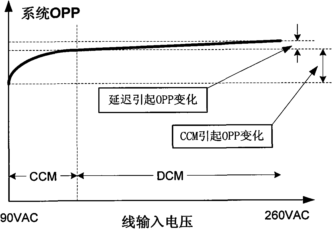
[0018] However, the duty cycle compensation method has a major defect: it causes the system OPP "recovery gap" to increase, and even causes the system to fail to start at low voltage.
Compared with the current duty cycle-by-cycle OCP compensation method, broken line or nonlinear duty cycle OCP compensation can greatly worsen sub-harmonic oscillation and large and small wave phenomena, which will lead to an increase in the OPP "recovery gap" of the system, and even cause the system to start at low voltage fail
[0019] To sum up, all duty-cycle-by-cycle OCP compensation methods so far cannot solve their inherent defects, so a new system and method is urgently needed to solve the above problems

Method used


Image

  • System and method for compensating maximum output power of switching power supply
  • System and method for compensating maximum output power of switching power supply
  • System and method for compensating maximum output power of switching power supply

Examples


Embodiment approach

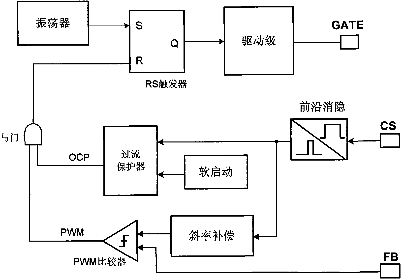
[0062] refer to Figure 8 , as an embodiment of the present invention, the processing module 31 in the above-mentioned overcurrent protector 3 includes:

[0063] A cyclic pulse generator 311, configured to generate several pulse signals (K1-Kn) and a clear signal CLR according to the PWM signal;

[0064] A clearing integrator 313, which generates a signal X0 according to the PWM signal and the clearing signal CLR output by the cycle pulse generator 311;

[0065] A sample-and-hold array 3121 and an arithmetic unit 3122, the sample-and-hold array 3121 is used to sample the duty cycle or pulse on-time of the several pulse signals (K1-Kn) to obtain several sampling signals (X1-Xn) , the operation unit 3122 performs operation processing on the sampling signal (X1-Xn) and the signal X0 output by the clearing integrator to generate a compensation signal Vcomp; specifically, the sample-and-hold array includes several groups of sampling units S1 / C1, S2 / C2 ,..., Sn / Cn, wherein S repre...


PUM


Abstract

The invention provides a system for compensating the maximum output power of a switching power supply, which comprises an oscillator, a pulse width modulation generator, an over-current protector, a driver and a leading edge blanking device, wherein the pulse width modulation generator generates a pulse width modulation signal according to a current sampling signal and a power feedback signal which are output by a power switching tube, a periodic clock signal output by the oscillator and an over-current protecting signal output by the over-current protector; the over-current protector outputsthe over-current protecting signal to the pulse width modulation generator according to the pulse width modulation signal and the current sampling signal; and the driver receives the pulse width modulation signal and outputs a power control signal; and the over-current protector comprises a processing module and an over-current protecting signal generation module. The invention also provides a method for compensating the maximum output power of the switching power supply; by the invention, the effective starting power of the switching power supply can not be changed, thus overcoming the defects that an OPP recovery clearance of the system in the prior art is increased and the starting of the system is unsuccessful when being at low pressure.

Description

technical field [0001] The invention relates to the technical field of switching power supply power control, in particular to a system and method for compensating the maximum output power of a switching power supply. Background technique [0002] Most switching power supplies use PWM (pulse width modulation) technology to control and adjust the output power. A variety of protection functions are set inside the switching power converter to avoid permanent damage to the system, such as over-voltage protection (OVP), over-current protection (OCP), over-temperature protection (OTP), etc. Among them, the over-current protection (OCP) is usually a cycle-by-cycle behavior, which limits the maximum current of the switching device and thus limits the maximum power output by the switching power converter, which is reflected in the system as the over-power protection (OPP). Over-power protection (OPP) limits the maximum output power of the system to prevent thermal runaway of the powe...

Claims


Application Information

Patent Timeline
IPC IPC(8): H02M7/217H02M1/32
Inventor 林官秋叶俊胡伟明方俊生
Owner 杨媛媛
Learn More