
Compound excitation permanent magnet synchronous generator for electric vehicles

A compound excitation and electric vehicle technology, applied in the field of motors, can solve the problems of synchronous/permanent magnet compound excitation motor with many voltage harmonics, magnetic field adjustment, difficulty in weak field expansion, increased volume and weight, etc., and achieve convenient voltage regulation. , the effect of small loss and improved performance indicators

Inactive Publication Date: 2010-03-03
苏州工业园区美能新能源有限公司 +1
View PDF0 Cites 20 Cited by
  • Summary
  • Abstract
  • Description
  • Claims
  • Application Information

AI Technical Summary

Problems solved by technology

[0003] At present, compound excitation synchronous motors of various structures have the following defects: such as claw pole electric excitation permanent magnet synchronous motors, radial / axial compound excitation synchronous motors and annular stator transverse flux motors, etc., and the additional air gap in the electric excitation magnetic circuit Many, the axial magnetic field is restricted by the diameter of the motor, and the motor structure is complex; the synchronous / permanent magnet compound excitation motor has many voltage harmonics and large torque fluctuations; the synchronous / permanent magnet compound Low; the ferromagnetic loss of combined rotor compound excitation motor increases significantly with the speed; permanent magnet axial segmented motor, that is, the permanent magnet main generator part and the electric excitation auxiliary generator part are connected by a common set of stator cores through the rotating shaft, and there are various structures Various, but in fact there are two motors in the axial direction, and the volume and weight increase; the latter two motors are surface-mounted permanent magnets, which make it difficult to adjust the magnetic field and weaken the speed of the magnetic field, and there is no pole shoe protection, so there is a risk of demagnetization. Poor pressure regulation performance

Method used


Image

  • Compound excitation permanent magnet synchronous generator for electric vehicles
  • Compound excitation permanent magnet synchronous generator for electric vehicles
  • Compound excitation permanent magnet synchronous generator for electric vehicles

Examples


Embodiment Construction

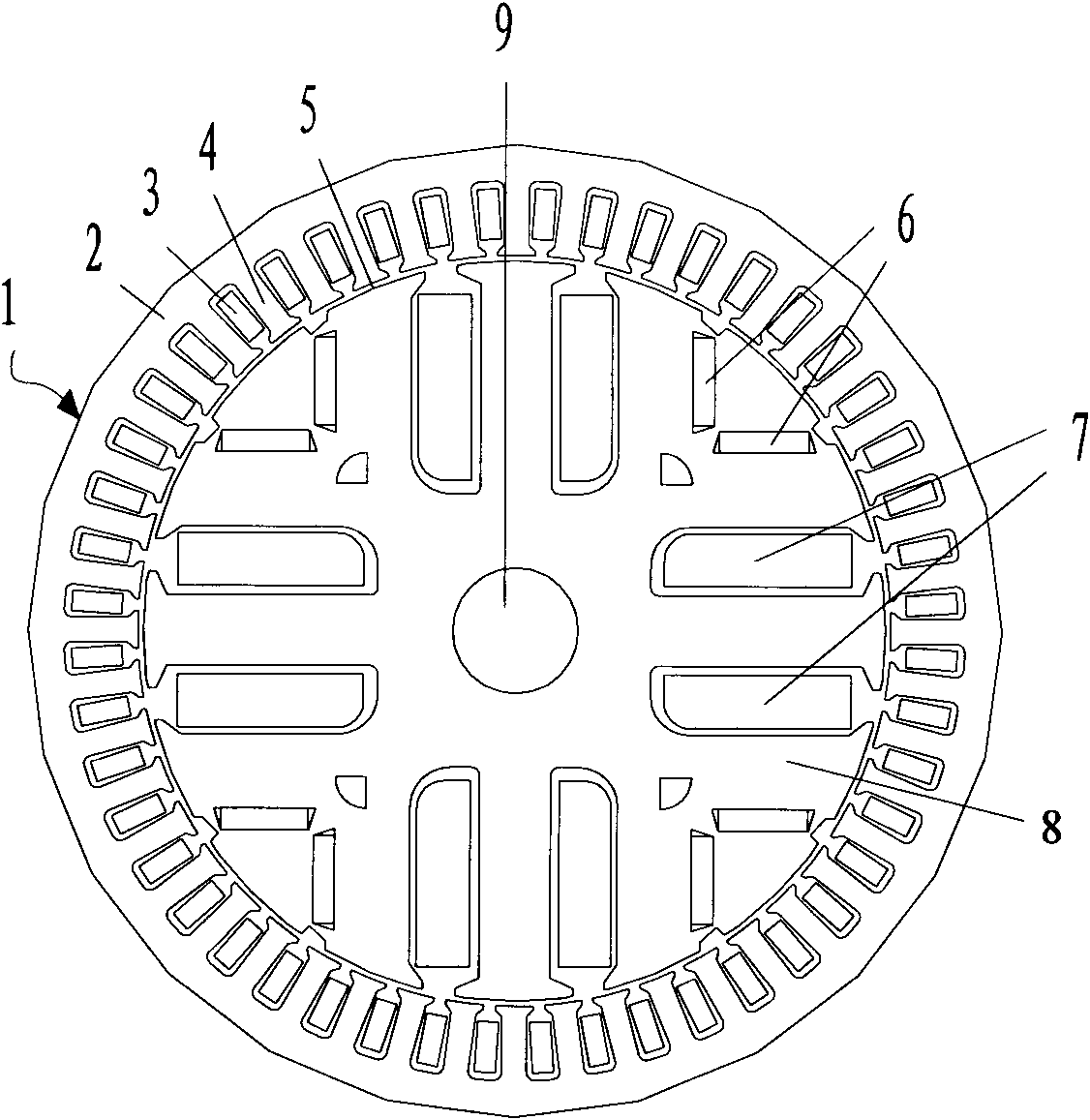
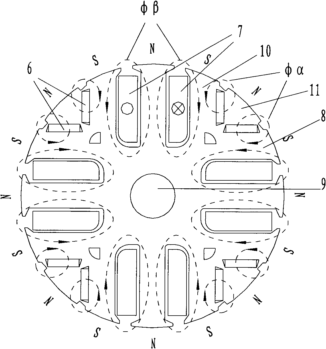
[0027] like figure 1 As shown, the compound excitation permanent magnet synchronous generator (HESG) for electric vehicles, the motor includes a casing and a stator and a rotor in the casing, the stator includes a stator core 1 and a stator winding fixed on the inner wall of the casing, and the stator core includes The stator yoke 2, the stator slot 3 and the stator teeth 4, the rotor includes the rotating shaft 9 and the rotor core 8, and the air gap 5 is formed between the stator and the rotor, wherein, the inner circumferential direction of the rotor core is provided with an auxiliary electric excitation winding 7 and a built-in V Type magnet 6. The two magnetic circuits are independent and share a set of stator core (armature). The armature induced potential is jointly generated by the permanent magnet and the auxiliary electric excitation winding. Adjusting the magnitude and direction of the DC excitation current in the electric excitation winding can easily adjust the a...


PUM


Abstract

The invention relates to a compound excitation permanent magnet synchronous generator for electric vehicles. An auxiliary electric excitation winding and built-in V-shaped magnetic steel are arrangedin a rotor iron core in the circumferential direction; the built-in V-shaped magnetic steel and a pole shoe form a permanent magnet pole, and the auxiliary electric excitation winding and an interwinding iron core form an excitation pole; the permanent magnet and the auxiliary electric excitation winding together generate armature induction potential, the air gap magnetic field can be adjusted conveniently by adjusting the magnitude and the direction of the DC excitation current in the electric excitation winding, and the purposes of high efficiency, energy saving and high-precision adjustmentof the voltage at an output end are achieved; meanwhile, the permanent magnet rotor is made of the V-shaped segmented magnetic steel, and holes are arranged in the pole shoe to lighten the weight ofthe rotor to avoid the high-speed deformation of the rotor; a groove is formed at the center of the pole shoe in the radial direction, and nonmagnetic good conductors are filled in the groove; and magnetism isolating grooves are arranged at two ends of the V-shaped magnetic steel, thereby inhibiting the static and dynamic armature reaction, improving the output voltage waveform, increasing the airgap magnetic density, reducing the magnetic leakage and increasing the output power. The compound excitation permanent magnet synchronous generator can smoothly operate at high power density, speed and precision.

Description

technical field [0001] The invention relates to a composite excitation permanent magnet synchronous generator for an electric vehicle, belonging to the technical field of motors. Background technique [0002] With the development of rare earth permanent magnet materials, the application of permanent magnet synchronous generators is becoming more and more extensive. Compared with electric excitation synchronous motors, permanent magnet excitation does not require excitation windings, and has the advantages of simple structure, reliable operation, small size, high efficiency, and high power density. But its biggest disadvantage is that the permanent magnet excitation cannot be adjusted. As a motor, it is impossible to achieve weak magnetic field expansion and wide constant power speed regulation by adjusting the excitation; as a generator, due to the high coercive force of the rotor permanent magnet, the generator The output voltage of the permanent magnet synchronous generat...

Claims


Application Information

Patent Timeline
Patent Type & Authority Applications(China)
IPC IPC(8): H02K21/14H02K1/27
CPCY02T10/641Y02T10/64
Inventor 胡岗林德芳胡溢文陈锋
Owner 苏州工业园区美能新能源有限公司
Learn More