Lifting device

A technology for lifting devices, workpieces, applied in the direction of transportation and packaging, load hanging elements, etc.

Inactive Publication Date: 2010-02-24
海雷廷·迪尔西兹
View PDF3 Cites 7 Cited by
  • Summary
  • Abstract
  • Description
  • Claims
  • Application Information

AI Technical Summary

Problems solved by technology

[0004] In known lifting devices, it is often a problem that the lifting device must be correctly positioned relative to the workpiece to be lifted, so that a safe lifting can be ensured

Method used


Image

  • Lifting device

Examples


Embodiment Construction

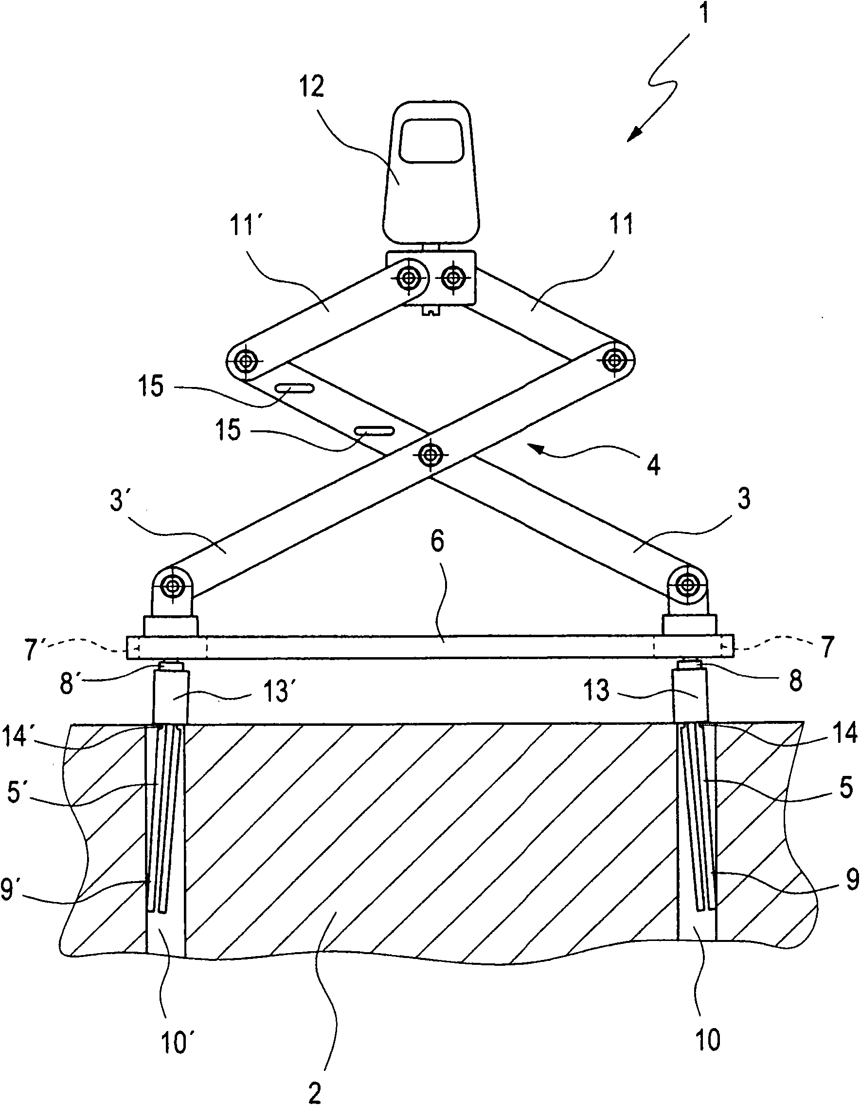
[0014] according to figure 1 , a lifting device 1 according to the invention for lifting a workpiece 2, in particular for lifting a cylinder head, comprises a scissor link 4 with two arms 3 and 3' and two rod-shaped The gripping arms 5 and 5'. Furthermore, the lifting device 1 includes a cross member 6 which has at least two axially adjacent elongated holes 7 and 7 ′ extending in the axial direction of the cross member 6 . The elongated holes 7 and 7 ′ are here arranged in each case in the region of one longitudinal end of the cross member 6 . The two gripping arms 5 and 5' are guided through the respective elongated hole 7, 7' and each have a fastening element 8 or 8' in order to prevent unintentional pulling out of the associated elongated hole 7, 7'. By means of the fastening elements 8 , 8 ′, the crossbeam 6 is prevented from falling when the lifting device 1 is raised.

[0015] according to figure 1 , each of the two gripping arms 5, 5' is rotatable about an axis exte...


PUM


Abstract

The present invention relates to a lifting device for lifting a workpiece. Said lifting device comprises a scissor-type linkage having two arms, and two rod-shaped gripper arms that are articulated thereto. The lifting device further comprises a crossbar, which has at least two axially adjacent elongated holes extending in the axial direction of the crossbar. The two gripper arms are each guided through the associated elongated hole and can be pivoted about an axis extending transversely to the longitudinal direction and transversely to the passage direction of the associated elongated hole, thus enabling a canting of the free gripper arm ends in an associated lifting opening of the workpiece, particularly of a cylinder head when lifting the same.

Description

technical field [0001] The invention relates to a lifting device for lifting a workpiece according to the preamble of claim 1 . Background technique [0002] For example, a device of this type is known from DE 20 2005 007 464 U1, which comprises two arms forming a pliers, said arms respectively comprising a lever arm and a gripping arm with a gripping element at its free end, wherein each of the pliers An arm is pivotably mounted between the lever arm and the gripper arm for opening and closing the pliers. Furthermore, the lifting device has a transverse beam on which the two arms of the pliers are pivotably connected at a distance from one another and each lever arm has one or more points of engagement for connection to a non-rigid traction device. [0003] Other lifting devices are known, for example, from DE 3907200C1, JP 09124267A and DD 251721A1. [0004] In known lifting devices, it is often a problem that the lifting device has to be correctly positioned relative to...

Claims


Application Information

Patent Timeline
Patent Type & Authority Applications(China)
IPC IPC(8): B66C1/42B66C1/66
CPCB66C1/66B66C1/422
Inventor 海雷廷·迪尔西兹
Owner 海雷廷·迪尔西兹
Why Eureka
Try Eureka