
Ceramic high-efficiency air self-preheating type combustor

A high-efficiency air and burner technology, applied to gas fuel burners, burners, combustion methods, etc., can solve the problems of large gas volume, high flame temperature, and large harmful gas emissions, so as to reduce emissions and improve gas mixing state , the effect of increasing the surface area

Active Publication Date: 2010-02-24
FOSHAN KEHAO COMBUSTION EQUIP MFG
View PDF0 Cites 14 Cited by
  • Summary
  • Abstract
  • Description
  • Claims
  • Application Information

AI Technical Summary

Problems solved by technology

[0002] At present, common kiln burners such as figure 1 As shown, it includes an air housing 1' with an air inlet 11' and a gas pipe 2' installed in it. An ignition electrode 3' is located inside the gas pipe 2'. When in use, the air flows from the air inlet 11' enters the air shell 1', and the combustible gas enters it from the gas inlet at the rear end of the gas pipe 2', and is mixed with air in a certain proportion at the mixing head 4' at the front end of the gas pipe 2' and is ignited The electrode 3' ignites and burns to form a stable flame. Although the structure of the burner with this structure is simple and the manufacturing cost is low, due to the structure, the burner consumes a large amount of gas during the combustion process. At the same time, the front end of the burner The flame temperature is high, and the harmful gas emission is large. In view of the above shortcomings, it is necessary to make improvements

Method used


Image

  • Ceramic high-efficiency air self-preheating type combustor
  • Ceramic high-efficiency air self-preheating type combustor
  • Ceramic high-efficiency air self-preheating type combustor

Examples


Embodiment Construction

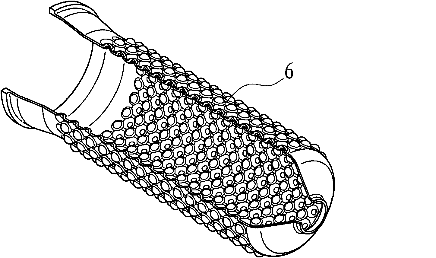
[0014] refer to figure 2 , image 3 , a ceramic high-efficiency air self-preheating burner, including a ceramic air duct 1 and a gas pipe 2 installed therein, an ignition electrode 3, and a ceramic combustion chamber 4, and the ceramic combustion chamber 4 is placed at the front end of the ceramic air duct 1 At the opening, the gas pipe 2 and the front end of the ignition electrode 3 protrude into the ceramic combustion chamber 4, and the rear end of the ceramic air duct 1 is equipped with an air intake housing 5 with an air inlet 51, which is located in the ceramic air duct 1 The outer cover is equipped with a ceramic heat exchanger 6, and the outer surface of the ceramic heat exchanger 6 is provided with a plurality of concave-convex small spherical surfaces or multiple groups of concave-convex fins, and the gap between its inner wall and the outer wall of the ceramic air duct 1 is the same as that of the air shell 5 In the same way, a ceramic flue gas conduit 7 is set out...


PUM


Abstract

The invention discloses a ceramic high-efficiency air self-preheating type combustor comprising a ceramic air guide pipe, a gas pipe installed in the ceramic air guide pipe, an ignition electrode anda ceramic combustion cavity, wherein the ceramic combustion cavity is arranged at the position of an opening at the front end of the ceramic air guide pipe; the front ends of the gas pipe and the ignition electrode extend into the ceramic combustion cavity; an air-intake shell with an air inlet is sleeved outside the rear end of the ceramic air guide pipe, a ceramic heat exchanger is sleeved outside the ceramic air guide pipe, the outer surface of the ceramic heat exchanger is provided with a plurality of concave-convex small spherical surfaces or groups of concave-convex fins, a gap positioned between the inner wall of the ceramic heat exchanger and the outer wall of the ceramic air guide pipe is communicated with the air-intake shell, a ceramic smoke gas guide pipe is also sleeved outside the ceramic heat exchanger, and the rear end of the ceramic smoke gas guide pipe is provided with a smoke gas outlet. The invention has reasonable structure, little energy consumption and harmful gas exhaust during combustion and high temperature resistance and is a ceramic high-efficiency air self-preheating type combustor widely applied into a kiln.

Description

technical field [0001] The invention relates to a kiln burner, in particular to a ceramic high-efficiency air self-preheating burner. Background technique [0002] At present, common kiln burners such as figure 1 As shown, it includes an air housing 1' with an air inlet 11' and a gas pipe 2' installed in it. An ignition electrode 3' is located inside the gas pipe 2'. When in use, the air flows from the air inlet 11' enters the air shell 1', and the combustible gas enters it from the gas inlet at the rear end of the gas pipe 2', and is mixed with air in a certain proportion at the mixing head 4' at the front end of the gas pipe 2' and is ignited The electrode 3' ignites and burns to form a stable flame. Although the structure of the burner with this structure is simple and the manufacturing cost is low, due to the structure, the burner consumes a large amount of gas during the combustion process. At the same time, the front end of the burner The flame temperature is high, a...

Claims


Application Information

Patent Timeline
Patent Type & Authority Applications(China)
IPC IPC(8): F23D14/22F23D14/66
CPCY02E20/34
Inventor 叶青
Owner FOSHAN KEHAO COMBUSTION EQUIP MFG
Learn More