
Lifting garbage compressor

A garbage compressor and lifting technology, which is applied in the direction of presses, garbage conveying, lifting devices, etc., can solve the problems of lowering the height of column buildings, short strokes of lifting cylinders, and complex structures, and achieve energy saving, short strokes, and stress small area effect

Active Publication Date: 2010-02-24
吉林前沅专用汽车制造股份有限公司
View PDF2 Cites 24 Cited by
  • Summary
  • Abstract
  • Description
  • Claims
  • Application Information

AI Technical Summary

Problems solved by technology

[0004] An object of the present invention is to provide a lifting device for a lifting garbage compressor, which has a short stroke of the lifting cylinder, a long lifting height, a fast lifting speed, high working efficiency, simple structure, convenient maintenance, and can significantly reduce the height and height of the column. The building height of the factory building; another object of the present invention is to provide a compression mechanism and a push-out mechanism of a lift-type garbage compressor, so that the pressure head can work independently on the push head to perform small-area, short-stroke compression, and then combine with the push head A whole area is released to solve the problems of uneven compression, complex structure and waste of energy

Method used


Image

  • Lifting garbage compressor
  • Lifting garbage compressor
  • Lifting garbage compressor

Examples


Embodiment Construction

[0025] Embodiment is described in detail below in conjunction with accompanying drawing:

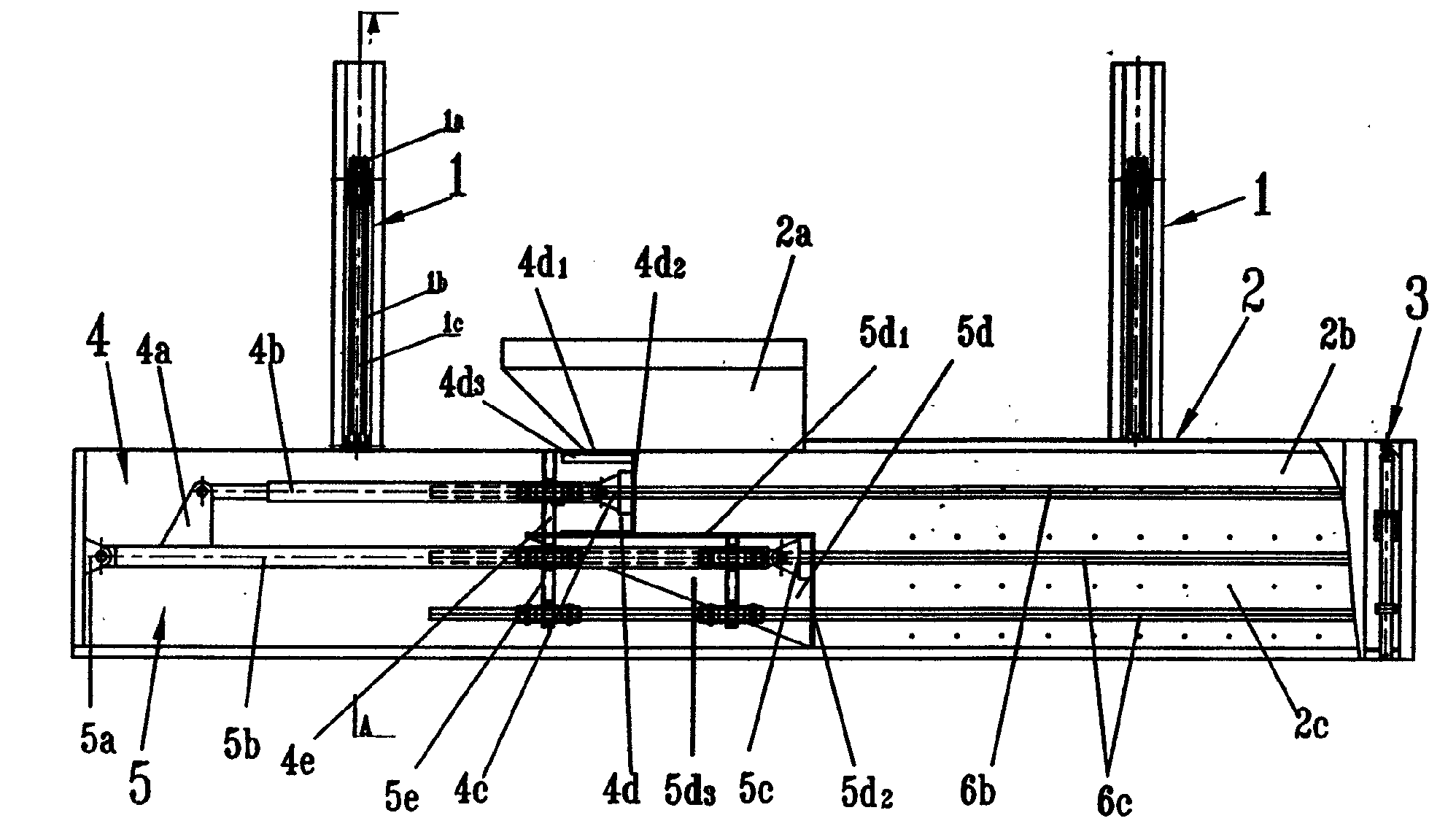
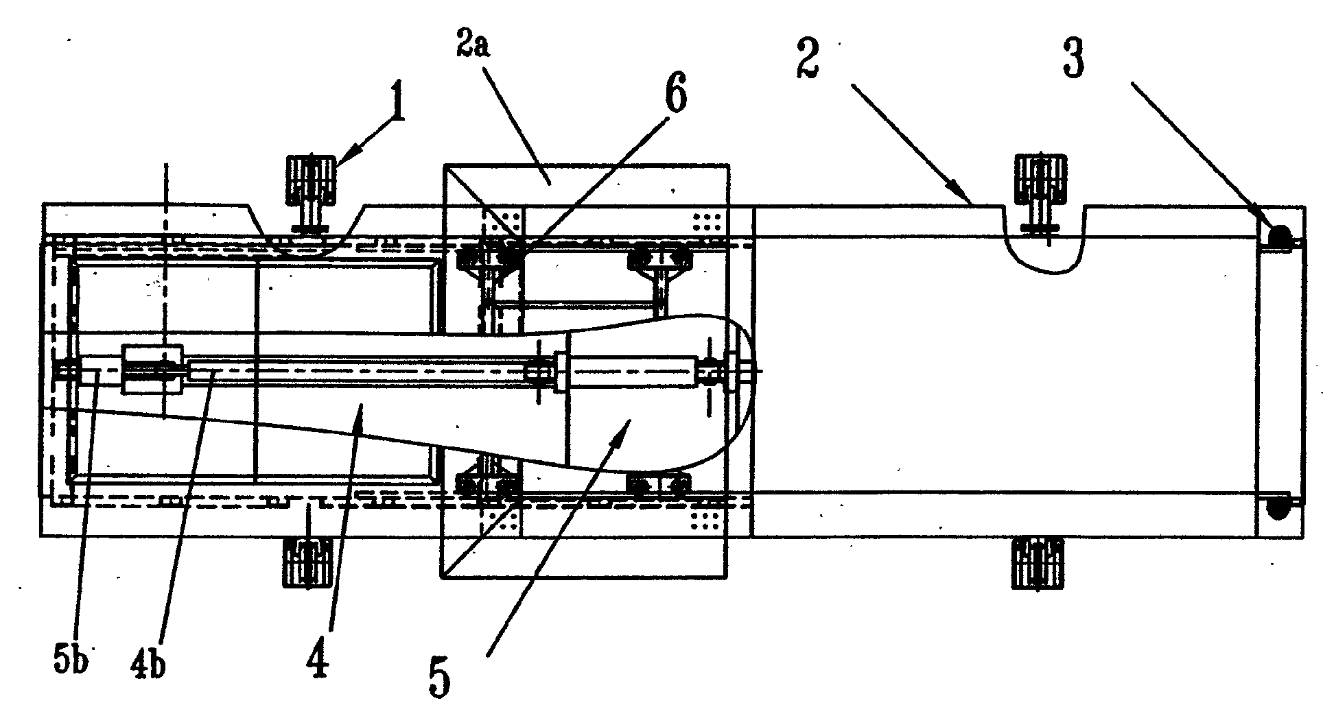
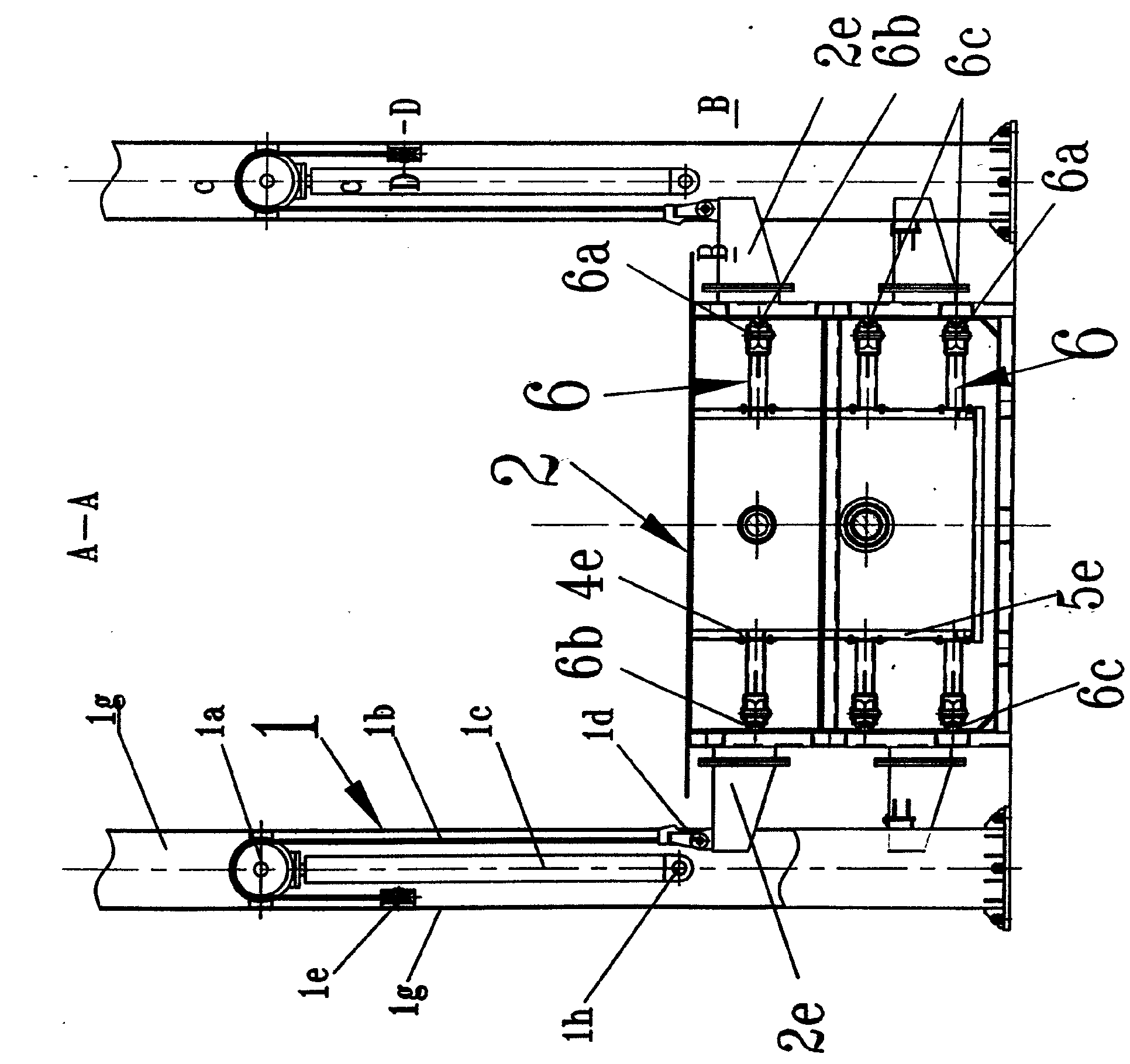
[0026] Lifting garbage compactor, (see figure 1 , figure 2 ) includes a lifting device 1, a garbage volume box 2 with a hopper 2a on the top and a gate mechanism 3 at the front end outlet, a garbage compression mechanism 4 and a push-out mechanism 5 placed in the garbage volume box, (see image 3 , Figure 4 , Figure 5 , Figure 6 ) The two sides of the box body of the garbage volume box 2 are fixed with cantilever beams 2e; the lifting device 1 is composed of a column 1g, an oil cylinder lifting mechanism, a pulley and sliding rope transmission mechanism; the column cross section is concave and hollow and is shaped on The opening is pressed and formed with a steel plate, and the cavity is respectively inserted into the oil cylinder lifting mechanism and the pulley and rope transmission mechanism from the opening; the oil cylinder lifting mechanism is composed of the oil cylinder 1...


PUM


Abstract

The invention relates to a lifting garbage compressor. The lifting garbage compressor comprises a lifting device 1, a gate mechanism 3, a garbage containing box 2, a garbage compressing mechanism 4 and a pushing mechanism 5. The invention is characterized in that: an upright column 1g of the lifting device has a dent hollow cross section and is provided with an opening, a built-in oil cylinder lifting mechanism and a pulley sliding-rope transmission mechanism; the lifting mechanism is composed of a lifting oil cylinder 1c, a piston 1y, a pulley base 1j and an oil cylinder base 1h; the pulley sliding-rope transmission mechanism is composed of a transmission pulley 1a, a sliding-rope 1b, a bearing pulley 1e and a bearing support 1f; the middle part of the sliding-rope is wound the bearing pulley; two parts of the sliding-rope are wound to the transmission pulley, and both ends of the sliding-rope are hinged on the cantilever beams 2e of the garbage containing box with the rope clamps 1d;a pushing-out mechanism 5 is placed at the back half part of the garbage containing box, and a compressing mechanism 4 is placed above the pushing-out mechanism 5. The lifting height of the lifting garbage compressor is two times of the oil cylinder stroke; the heights of the upright column and the workshop are reduced for more than 15%; and furthermore the compressing mechanism of the inventionhas the advantages of excellent compression effect and high efficiency.

Description

Technical field: [0001] The invention belongs to the technical field of urban environmental sanitation equipment, and in particular relates to a lift-type garbage compressor. Background technique: [0002] At present, the lift-type garbage compressor has Chinese patent application number 200810062297.9, and the publication number is CN10298195A; it discloses a "buried garbage compressor" composed of a garbage bin, a compression mechanism, a push-out mechanism and a lifting device. Its lifting device adopts Lift the cylinder to realize the rising or falling of the garbage box. The lifting cylinder is installed on the foundation of the pit, and the end of the cylinder is pinned to the lifting seat to drive the garbage box up and down. This structure determines that the lifting height of the box must be equal to the stroke of the cylinder. That is 1:1, and the height of the column must be at least twice the lifting height or the stroke of the cylinder. The disadvantages of thi...

Claims


Application Information

Patent Timeline
IPC IPC(8): B30B9/00B30B15/00B65F9/00B66F11/00
Inventor 孙凤山隋德军张德喜杨永吉谢海瑞张伟杰王永吉
Owner 吉林前沅专用汽车制造股份有限公司
Learn More