Automatic loading and unloading device aiming at crankshaft

A technology of automatic loading and unloading, crankshaft, applied in metal processing and other directions, can solve the problems of high labor intensity and scratches on the surface of the crankshaft, and achieve the effect of improving work efficiency and saving time for loading and unloading.

Active Publication Date: 2010-02-24
BEIJING NO 2 MACHINE TOOL WORKS
View PDF0 Cites 4 Cited by
  • Summary
  • Abstract
  • Description
  • Claims
  • Application Information

AI Technical Summary

Problems solved by technology

However, the current cylindrical grinding machines for crankshafts generally use automatic equipment such as fully enclosed protective covers, follow-up center frames, and flip radial gauges. The commonly used crankshaft loading and unloading methods rely on manual loading and unloading or controlled crane loading and unloading, which is not only labor-intensive , and often scratches the surface of the crankshaft

Method used


Image

  • Automatic loading and unloading device aiming at crankshaft
  • Automatic loading and unloading device aiming at crankshaft

Examples


Embodiment Construction

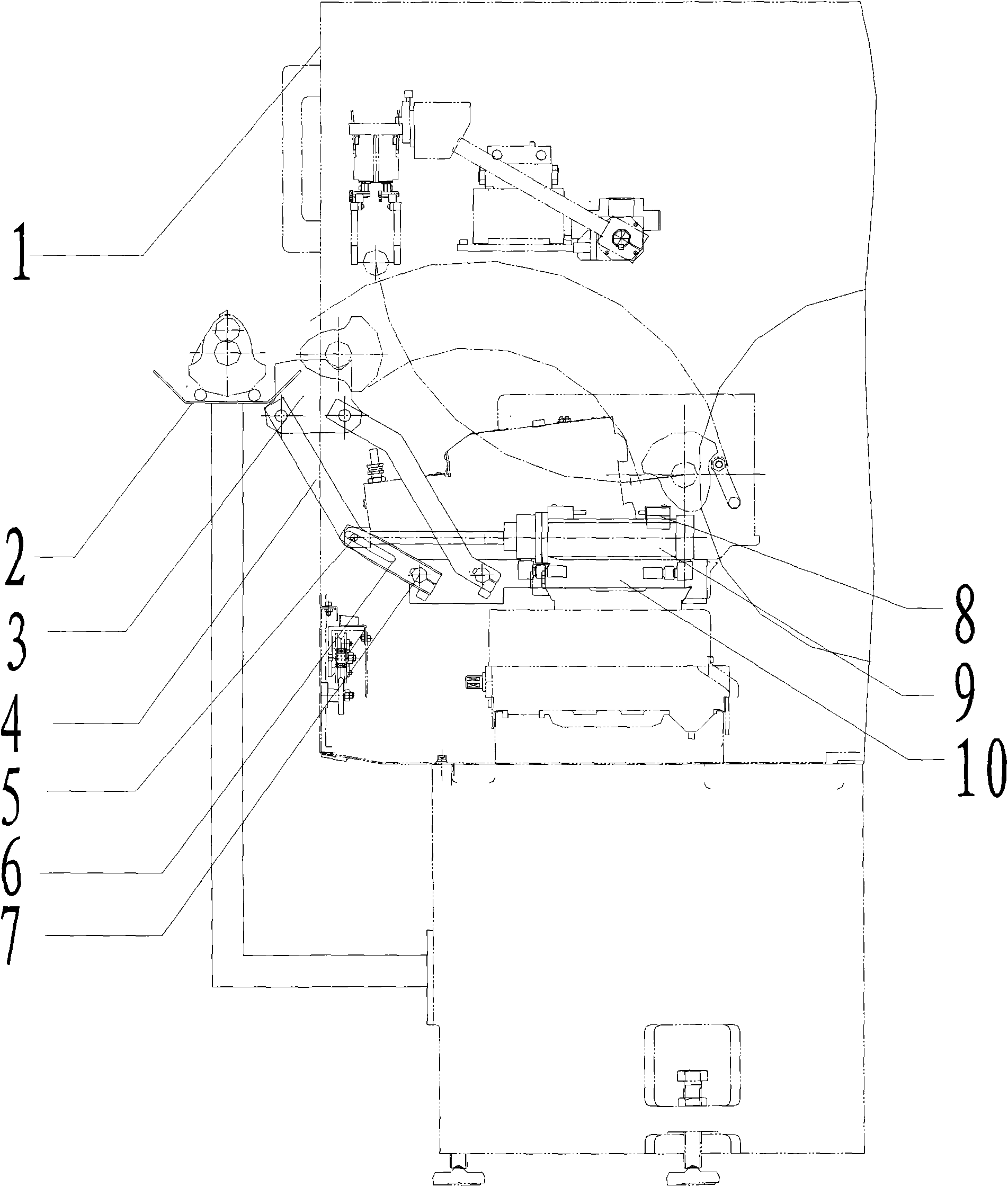
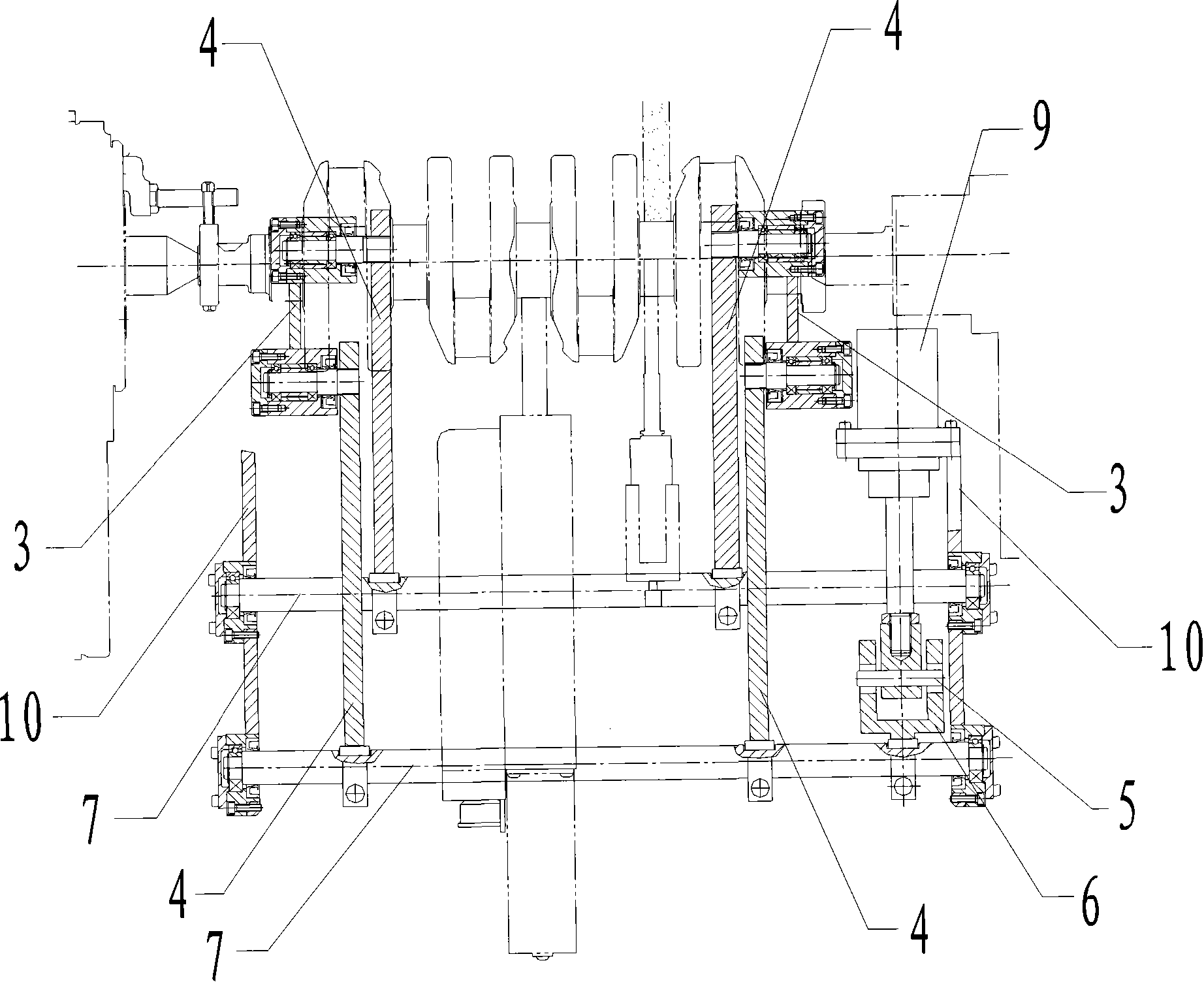
[0018] figure 1 with figure 2 It shows the application of the automatic loading and unloading device for the crankshaft provided by the present invention on the CNC grinding machine. The automatic loading and unloading device includes two left and right swing frames, and the swing frames are composed of two front and rear swing arms 4 and a workpiece bracket 3 The front and rear ends of the workpiece bracket are respectively hinged with the upper ends of the front and rear swing arms, so that when the swing arm drives the workpiece bracket to move, the workpiece bracket remains horizontal and does not make it The crankshaft transported on the top falls, and the lower ends of the front and rear swing arms are respectively connected to the front and rear shafts 7 through key couplings, so that when the shafts rotate, the swing arms can rotate accordingly, and the front and rear shafts pass through The bearing is connected with the frame 10 in rotation, and the frame for instal...


PUM


Abstract

The invention relates to an automatic loading and unloading device aiming at a crankshaft, comprising a left swinging bracket and a right swinging bracket, wherein, the swinging brackets are composedof a front swinging arm, a rear swinging arm and a workpiece bracket; two sides of the workpiece bracket are respectively hinged with upper ends of a left swinging arm and a right swinging arm, and lower ends of the left swinging arm and the right swinging arm are respectively connected with a front rotating shaft and a rear rotating shaft; the front rotating shaft and the rear rotating shaft arerotatablely connected with a frame by a bearing; and one of the front rotating shaft and the rear rotating shaft is a driving shaft, the driving shaft is connected with a hydraulic drive mechanism, and the hydraulic drive mechanism is provided with a control circuit. In the invention, a hydraulic cylinder of the hydraulic drive mechanism drives the swinging brackets to swing for automatically loading and unloading, thus improving working efficiency, reducing labor intensity and avoiding scratch possibility on a workpiece during a manual loading and unloading process.

Description

technical field [0001] The invention relates to an automatic loading and unloading device, in particular to an automatic loading and unloading device for crankshafts, which belongs to the field of metal cutting and can be used for loading and unloading workpieces of cylindrical grinding machines for crankshaft processing and other machine tools. Background technique [0002] In order to meet the needs of the new industrial structure, especially the rapid expansion of the modern automobile manufacturing industry, the requirements for the efficiency of the corresponding machine tools are constantly increasing. However, the current cylindrical grinding machines for crankshafts generally use automatic equipment such as fully enclosed protective covers, follow-up center frames, and flip radial gauges. The commonly used crankshaft loading and unloading methods rely on manual loading and unloading or controlled crane loading and unloading, which is not only labor-intensive , and of...

Claims


Application Information

Patent Timeline
IPC IPC(8): B23Q7/00
Inventor 蔡斌刘德鉁李伟华王波穆东辉
Owner BEIJING NO 2 MACHINE TOOL WORKS
Why Eureka
Try Eureka