Method and device for spreading conducting wire in micro-tension overhead suspension way

A micro-tension and wire technology, applied in overhead installation, overhead line/cable equipment, cable installation, etc., can solve the problems of high construction cost, economic loss of power supply enterprises, power consumption enterprises, environmental damage, etc., and improve construction efficiency , reduce construction costs, and protect the environment

Inactive Publication Date: 2010-02-17
贵州惠水思宇电力实业有限公司
View PDF0 Cites 8 Cited by
  • Summary
  • Abstract
  • Description
  • Claims
  • Application Information

AI Technical Summary

Problems solved by technology

Due to the high braking tension, the power loss during payout is also large, so the payout section cannot be too long, generally only about 10KM; this requires setting up several stretching sites in the entire erection line, which not only reduces the construction cost High, low efficiency, but also occupy a lot of land, causing environmental damage
In addition, when crossing areas with relatively dense power lines, in order to ensure safety, it is generally required to suspend power supply to existing power lines. Inconvenience; if the construction is carried out without power supply, a spanning frame or a spanning net must be built above the crossed line; even so, accidents that the conductor falls and the spanning frame or spanning net is smashed still occur from time to time

Method used


Image

  • Method and device for spreading conducting wire in micro-tension overhead suspension way
  • Method and device for spreading conducting wire in micro-tension overhead suspension way
  • Method and device for spreading conducting wire in micro-tension overhead suspension way

Examples


Embodiment Construction

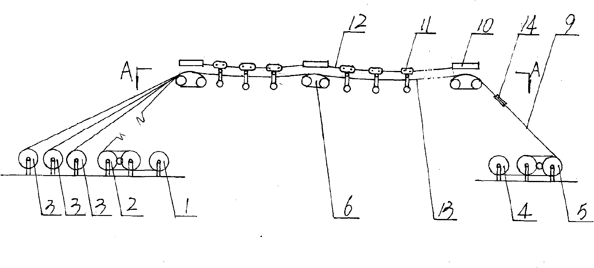
[0033] Below in conjunction with accompanying drawing and specific embodiment the present invention will be further described:

[0034] Such as Figure 1~5 Shown: the method provided by the present invention comprises launching guide rope, traction rope and lead wire, and specific method is as follows:

[0035] 1) Set a pay-off reel 1, a tension machine 2 and a wire reel 3 at the beginning of the line, and set a recovery reel 4 and a tractor 5 at the end of the line;

[0036] 2) Temporarily fix the electric conveyor 6 on the cross arm 10 of each base tower of the line;

[0037] 3) Utilize the aircraft to deploy the guide ropes 7 one by one in the wire grooves of the electric conveyors 6 from the beginning to the end of the line, and then wind the rope ends of the guide ropes 7 on the recovery disc 4 through the tractor 5;

[0038] 4) Take out the traction rope 9 from the pay-off reel 1, pass the tension machine 2 and connect the guide rope 7 through the connector 8, start th...


PUM


Abstract

The invention discloses a method and a device for spreading a conducting wire in a micro-tension overhead suspension way, which belong to a construction method and a construction device of overhead power transmission lines and the invention aims at providing a method for constructing the overhead power transmission lines with high efficiency and no power failure for spanning electric power lines and a device for realizing the method. The invention completes the work of erecting a conducting wire (13) on cross arms (10) by devices, such as a wire release disk (1), a tension machine (2), a wiredisk (3), a connector (8), a recovering disk (4), a tractor (5), an electric transporter (6), a hanging basket string and the like, wherein the wire release disk (1), the tension machine (2) and the wire disk (3) are arranged at the beginning end of a line, the connector (8) is connected between a guide rope (7) and a traction rope (9), the recovering disk (4) and the tractor (5) are arranged at the end of the line, the electric transporter (6) is fixed on the cross arms (10) and the hanging basket string is arranged between the cross arms (10). The invention does not need to arrange a middletraction field and a tension field, has the advantages of short construction period, small spreading tension, long wire release area section, little land occupation in construction and the like and isan advanced method for erecting the power transmission line.

Description

Technical field: [0001] The invention relates to a method for laying out wires in power lines, in particular to a method for laying out wires in overhead power lines; the invention also relates to a device for realizing the method. Background technique: [0002] As we all know, tension pay-off is a commonly used method for laying out overhead conductors; in order to ensure a certain distance between the conductor and the ground during pay-out, it is often necessary to brake the conductor with a large tension to make it suspend at high altitude. Due to the high braking tension, the power loss during payout is also large, so the payout section cannot be too long, generally only about 10KM; this requires setting up several stretching sites in the entire erection line, which not only reduces the construction cost High, low efficiency, but also occupy a large amount of land, causing environmental damage. In addition, when crossing areas with relatively dense power lines, in orde...

Claims


Application Information

Patent Timeline
IPC IPC(8): H02G1/02H02G7/00
Inventor 程永忠
Owner 贵州惠水思宇电力实业有限公司
Why Eureka
Try Eureka