Autotransformer with low-voltage compensation
An autotransformer, main transformer technology, applied in transformers, fixed transformers, variable transformers, etc., can solve problems such as incomplete compensation, incomplete compensation of low-voltage compensation, and inability to completely solve problems, and achieve the effect of solving voltage fluctuations
- Summary
- Abstract
- Description
- Claims
- Application Information
AI Technical Summary
Problems solved by technology
Method used
Image


Examples
Embodiment 1
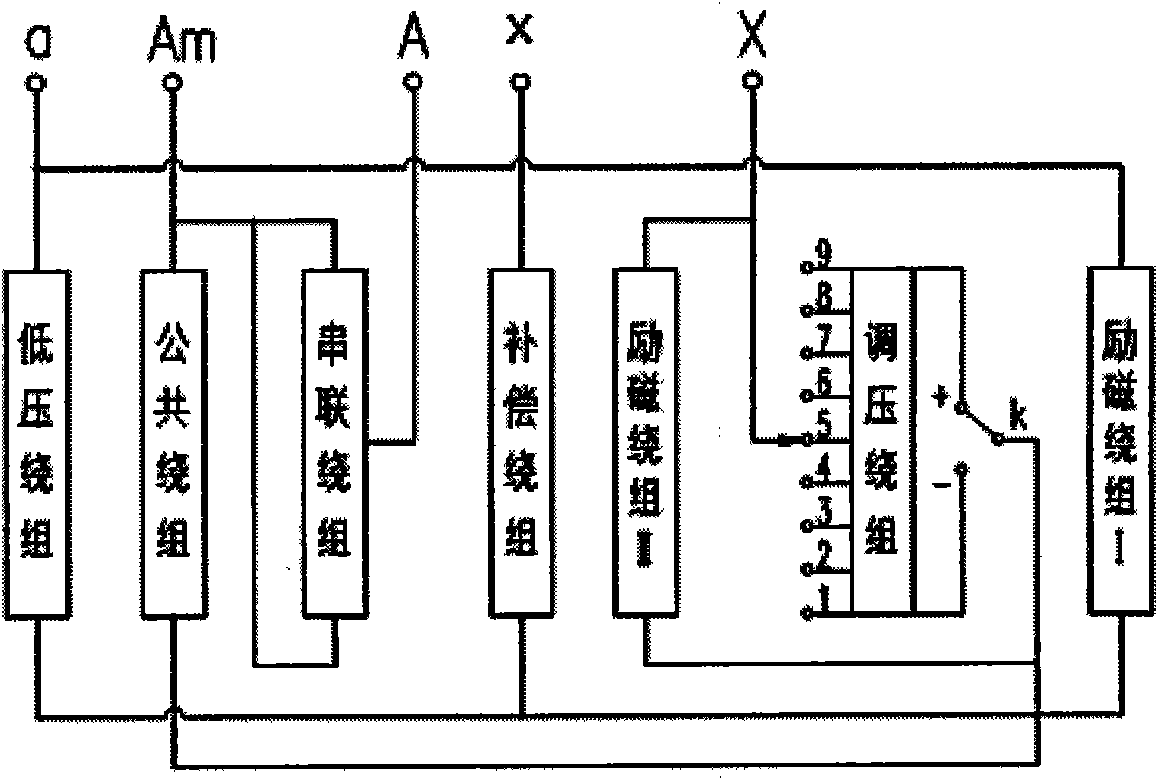
[0019] An autotransformer with low-voltage compensation, the wiring method is as follows image 3 As shown, it includes main transformer, voltage regulator and compensation device. The main transformer includes low-voltage winding, common winding and series winding; the voltage regulator includes voltage regulating switch k, voltage regulating winding and excitation winding I for exciting the voltage regulating winding; compensation The device includes a compensation winding and an excitation winding II for excitation of the compensation winding; the beginning of the low-voltage winding is connected to the beginning of the excitation winding I, and the leading end is the beginning of the low-voltage winding A, the end of the low-voltage winding is connected in series with the compensation winding, and the end of the excitation winding I is connected to the end of the compensation winding Connected, leading out to the low-voltage terminal x; the beginning of the common winding o...
Embodiment 2
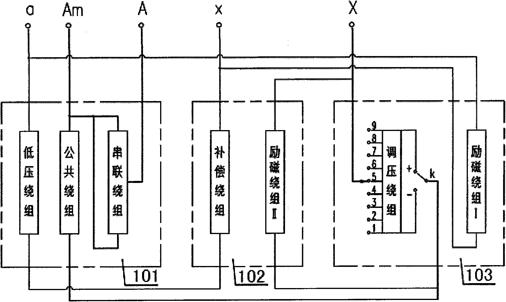
[0021] Such as image 3 As shown, the main transformer, the voltage regulator and the compensating device in Embodiment 1 are provided with separate bodies, respectively the main transformer body 101 , the voltage regulator body 103 and the compensating device body 102 . In the main transformer body 101, the arrangement of low-voltage windings, common windings and series windings is shown in Figure 4 ; In the voltage regulator body 103, the arrangement of the field winding I and the voltage regulating winding is shown in Figure 5 ; In the compensation device body 102, the arrangement of the excitation winding II and the compensation winding is shown in Figure 6 . Among them, the compensation winding is used to compensate the low-voltage side voltage; the excitation winding II is used to excite the compensation winding; the excitation winding I is used to excite the voltage regulating winding.
[0022] The invention can completely solve the problem of low-voltage voltage ...
PUM
 Abstract
Description
Claims
Application Information
 - R&D
- Intellectual Property
- Life Sciences
- Materials
- Tech Scout
- Unparalleled Data Quality
- Higher Quality Content
- 60% Fewer Hallucinations
Browse by: Latest US Patents, China's latest patents, Technical Efficacy Thesaurus, Application Domain, Technology Topic, Popular Technical Reports.
© 2025 PatSnap. All rights reserved.Legal|Privacy policy|Modern Slavery Act Transparency Statement|Sitemap|About US| Contact US: help@patsnap.com