
Fountain aeration spray head and manufacture method and use method thereof

A nozzle and aeration technology, applied in water aeration, chemical instruments and methods, sustainable biological treatment, etc., can solve the problems of large floor area, small air supply, complex equipment, etc.

Inactive Publication Date: 2011-04-20
TIANJIN WATER RESOURCES RES INST
View PDF0 Cites 0 Cited by
  • Summary
  • Abstract
  • Description
  • Claims
  • Application Information

AI Technical Summary

Problems solved by technology

In the traditional aeration device, the method of reducing the aperture of the air outlet is generally used to generate smaller-diameter air bubbles. This kind of aerator has defects such as small air supply, easy blockage of the air outlet, and low efficiency.
The devices using the air flotation method have their own advantages, but they generally have the disadvantages of high energy consumption, complicated equipment, large floor space, and excessively large bubble diameters. Excessively large bubble diameters will cause many problems. Proportional to the square of the diameter of the bubble, the bubbles rise fast and the flocs are not easy to bond, and the flocs are not easy to rise to the water surface
In addition, all sewage purification devices cannot change the aeration method according to the change of water quality, and at the same time, the arrangement of aeration devices in water areas in cities will affect the urban landscape.

Method used


Image

  • Fountain aeration spray head and manufacture method and use method thereof
  • Fountain aeration spray head and manufacture method and use method thereof
  • Fountain aeration spray head and manufacture method and use method thereof

Examples


Embodiment 1

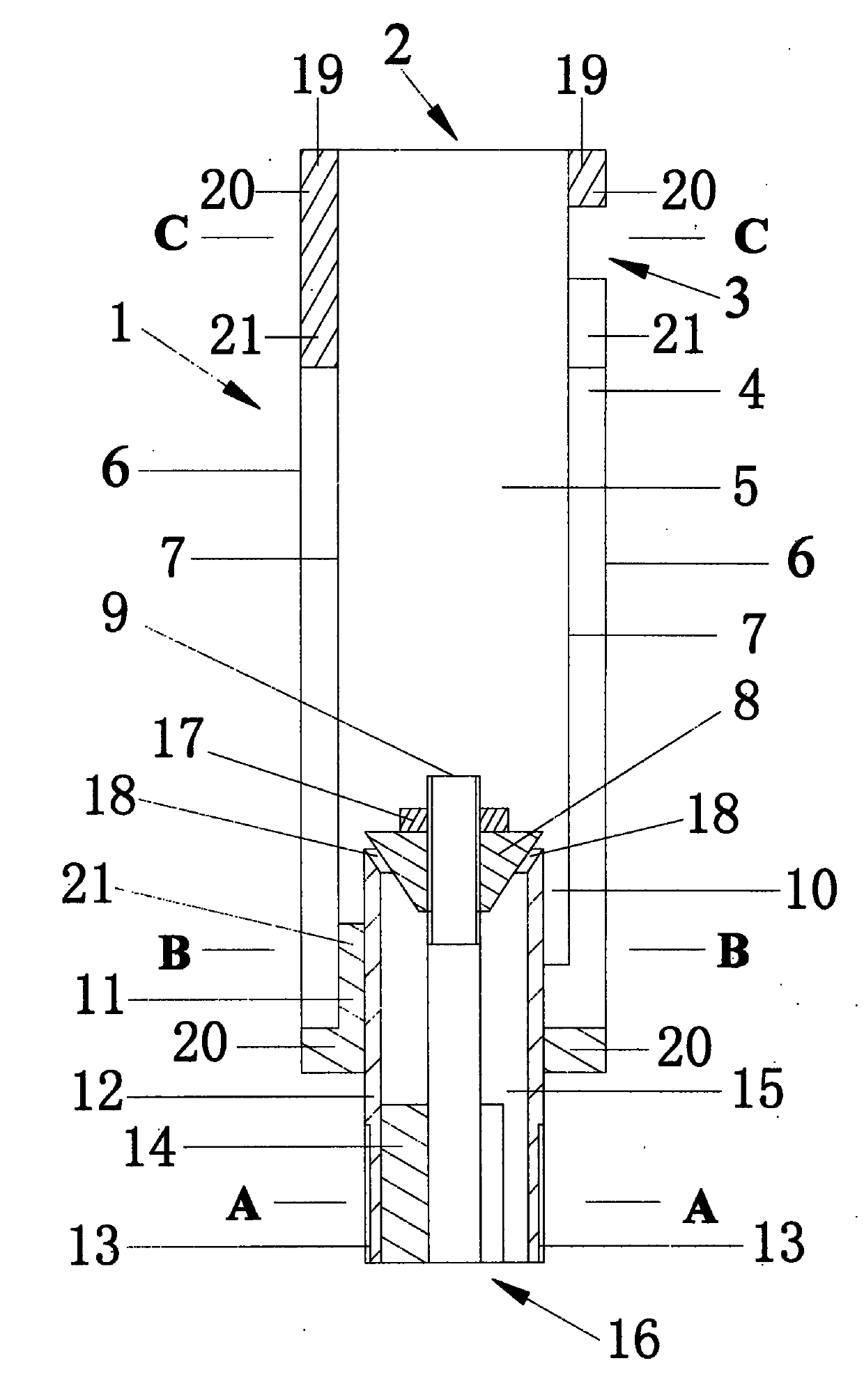
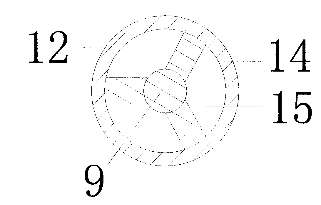
[0074] The nozzle body (1) is composed of the nozzle outer barrel (6), the nozzle inner barrel (7), the air-water mixing diversion cavity (5), the water source nozzle (12) and the flow regulator (9), passing through the cone diversion bracket (14). The lower flange bracket (11) and the upper flange bracket (19) are connected to form the sprinkler body (1). The water source nozzle (12) is in the shape of a hollow cylinder as a whole, and the central part is provided with a flow regulator (9), and the water source At least 3 cone-shaped deflector supports (14) are equidistantly arranged at the lower end of the nozzle (12). The two sides of the cone-shaped deflector support (14) are respectively connected to the inner wall of the water source nozzle (12) and the flow regulator (9) The outer walls are fixedly connected, and the conical deflector bracket (14) fixes the flow regulator (9) in the middle of the water source nozzle (12).

[0075] The cone-shaped deflector bracket (14) sep...

Embodiment 2

[0080] The outer wall of the water source nozzle (12) is fixedly provided with a lower flange bracket (11) around the outer wall. The lower part of the lower flange bracket (11) is an annular closing plate (20) in the shape of an eye ring, along the inner side of the annular closing plate (20) At least three flange plates (21) are arranged at equal intervals. The flange plates (21) protrude on the annular closing plate (20). The outer side of the annular closing plate (20) forms a protruding platform. The concave gap forms an air outlet (10), and the inner side of the lower end flange bracket (11) is fixedly connected with the outer wall of the water source nozzle (12).

[0081] The nozzle inner barrel (7) and the nozzle outer barrel (6) are hollow cylinders. The diameter of the nozzle inner barrel (7) is smaller than that of the nozzle outer barrel (6). The nozzle inner barrel (7) is set in the nozzle outer barrel (6), and the nozzle The lower end of the inner barrel (7) is fixe...

Embodiment 3

[0085] The upper end of the nozzle inner barrel (7) and the upper end of the nozzle outer barrel (6) are provided with an upper flange bracket (19), and one end of the upper flange bracket (19) is an annular closing plate (20), which is in the shape of an eye ring and is closed in a ring. At least 3 flange plates (21) are arranged at equal intervals on the plate (20), the flange plates (21) protrude on the annular closed plate (20), and the flange plates (21) are concave-shaped gaps between them. Form the air inlet (3).

[0086] The outer wall of the upper end of the sprinkler inner barrel (7) is fixedly connected with the inner side of the upper flange bracket (19), and the inner wall of the upper end of the sprinkler outer barrel (6) is fixedly connected with the outer side of the upper flange bracket (19). The annular closing plate (20) of the flange bracket (19) closes the air inlet passage (4) formed by the upper end of the inner barrel (7) of the nozzle and the upper end of...


PUM


Abstract

The invention relates to a fountain aeration spray head and a manufacture method and a use method thereof. A spray head main body comprises a spray head outer barrel, a spray head inner barrel, an air-water mixing flow guide cavity, a water source spray pipe and a flow regulator and is formed by connecting a tapered flow guide bracket, a lower end flange bracket and an upper end flange bracket; the center part of the water source spray pipe is provided with the flow regulator; the lower end flange bracket is fixedly arranged on the outer wall of the water source spray pipe; both end parts of the spray head inner barrel and the spray head outer barrel are fixedly provided with the lower end flange bracket and the upper end flange bracket respectively to form an air inlet passage to guide air to the air-water mixing flow guide cavity; and a mixed air-water mixing water source is sprayed from a nozzle to aerate a water source. The invention has scientific design conception, reasonable structure, convenient use, large and even aeration, favorable aeration effect, simple and easy installation and debugging, even air-water mixture, large fountain water shape diameter, attractive appearance, large air inflow, elegant white jade pillar water shape, nobleness, generosity, elegance and distinction and combines aeration and a waterscape together.

Description

Technical field [0001] The invention relates to a facility and method for aeration in water areas, in particular to a fountain aeration nozzle and a manufacturing method and a method of use. Background technique [0002] At present, human beings are facing the severe challenge of water pollution. Among them, domestic sewage is a major source of water pollution. Among all the natural elements that maintain human survival, ensure economic construction, and maintain social development, the importance of water is needless to say. However, with the acceleration of industrialization and urbanization, the world is facing the challenge of water shortage and serious pollution. China is particularly serious. It is one of the 13 water-scarce countries in the world. About half of the more than 600 cities in the country currently lack water. The water body does not flow and exchange all the year round, coupled with the wind direction and other reasons, the pollutants in the water area are ea...

Claims


Application Information

Patent Timeline
Patent Type & Authority Patents(China)
IPC IPC(8): C02F7/00
CPCY02W10/10
Inventor 汪长余刘学功罗智能
Owner TIANJIN WATER RESOURCES RES INST
Learn More