
Automatically-recording type ventilating dry humidity device

A technology for ventilation, dryness and wetness and automatic recording. It is applied in the directions of thermometers, measuring devices, and electrical devices. It can solve the problems of not reaching the micro-change state process, not reaching the value of the micro-change state process, and low sensitivity. Sensitivity and accuracy, the effect of avoiding measurement errors

Inactive Publication Date: 2010-02-10
SHANDONG INST OF POMOLOGY
View PDF0 Cites 5 Cited by
  • Summary
  • Abstract
  • Description
  • Claims
  • Application Information

AI Technical Summary

Problems solved by technology

Among the existing methods for recording these temperature and humidity parameters, one is to use manual real-time observation and recording. This method is not only time-consuming, laborious, and inefficient, but also fails to record and save the values ​​of the micro-change state process in time, especially easy The limit value is lost; another method is to use a device such as an Assmann ventilation psychrometer for observation. Since it cannot be converted into a digital signal, it cannot be recorded by the data acquisition and recording processor, and it cannot record and save the micro-change state process in time. It is also easy to lose the limit value; at the same time, due to the large probe and low sensitivity, the reaction speed is usually calculated in minutes, and the hysteresis is particularly obvious. It is difficult to capture the instantaneous change of temperature and humidity, especially the limit value is easy to lose. The limit values ​​of dry bulb temperature, wet bulb temperature and relative humidity are important data for studying the impact of environmental changes on agricultural ecology

Method used


Image

  • Automatically-recording type ventilating dry humidity device

Examples


Embodiment Construction

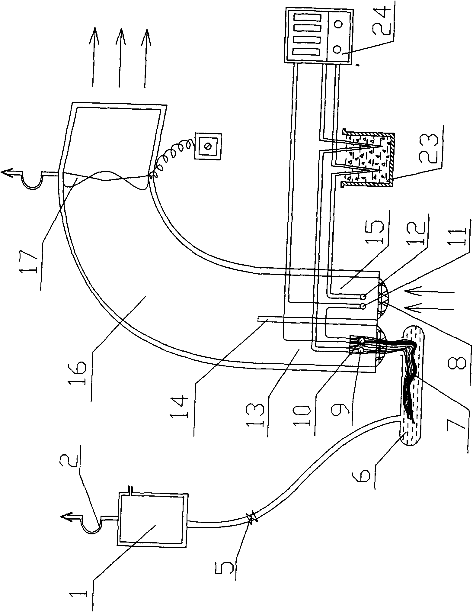
[0022] The accompanying drawing is an embodiment of the present invention, and this embodiment will be described in detail in conjunction with the accompanying drawings, including a large water reservoir 1, a hook 2, a regulating valve 5, a small water reservoir 6, an air duct pipe 16, a partition 14, and a fan 17. Net cover 8, thermocouple wet bulb 9, thermocouple temperature difference wet bulb 10, thermocouple temperature difference dry bulb 11, thermocouple dry bulb 12, moisturizing gauze 7, digital acquisition record processor 24 and thermostat 23; Among the examples, the large water storage device 1, the hook 2, the regulating valve 5 and the small water storage device 6 form a moisturizing device, and the upper end side of the large water storage device 1 is provided with a water filling and gas balance port, and the upper end of the large water storage device 1 The end face is provided with a hook 2 fixedly connected with it, the large water storage 1 is set to be conne...


PUM


Abstract

The invention relates to an automatically-recording type ventilating dry humidity device which comprises a moisturizing device, an air flue (16), a partition plate (14), a fan (17), a thermocouple wetbulb (9), a thermocouple temperature difference wet bulb (10), a thermocouple temperature difference dry bulb (11), a thermocouple dry bulb (12), moisturizing gauze (7), a digital collecting and recording processor (24) and a thermostat (23), wherein a measuring port of the air flue pipe (16) is divided into a measuring cavity I (13) and a measuring cavity II (15) by the partition plate (14); thethermocouple wet bulb (9) and the thermocouple temperature difference wet bulb (10) are arranged in the measuring cavity I (13) of the air flue pipe (16); the thermocouple temperature difference drybulb (11) and the thermocouple dry bulb (12) are arranged in the measuring cavity II (15) of the air flue pipe (16); and the copper electrode output ends of the thermocouple temperature difference wetbulb (10) and the thermocouple temperature difference dry bulb (11), and the copper electrode output ends and the constantan electrode output ends of the thermocouple wet bulb (9) and the thermocouple dry bulb (12) are connected with the inlet end of the digital collecting and recording processor (24), thereby being difficult to lose a limit value and recording and storing a numerical value in the micro-change state process in time.

Description

1. Technical field [0001] The invention relates to an automatic recording type ventilation dry-humidity temperature device, in particular to an automatic recording type dry-wet temperature device suitable for monitoring the micro-change state of the ecological environment temperature and humidity. 2. Background technology [0002] Dry bulb temperature, wet bulb temperature and relative humidity are important factors of the agricultural ecological environment. Accurate and timely recording of these temperature and humidity parameters is a very important basis for future research on the impact of environmental changes on agricultural ecology. Therefore, recording these temperature and humidity parameters The parameters of the device are very important. Among the existing methods for recording these temperature and humidity parameters, one is to use manual real-time observation and recording. This method is not only time-consuming, laborious, and inefficient, but also fails to ...

Claims


Application Information

Patent Timeline
IPC IPC(8): G01K7/02G01N25/64
Inventor 鲁墨森王淑贞刘晓辉赵峰于兰岭鲁宁琳
Owner SHANDONG INST OF POMOLOGY
Learn More