
Panel strip for vehicle

A molding and automotive technology, applied to vehicle parts, transportation and packaging, etc., can solve problems such as poor bonding, staggering, and high resistance of soft resin parts, and achieve the effect of preventing poor installation

Active Publication Date: 2010-02-10
KATAYAMA KOGYO CO LTD
View PDF8 Cites 4 Cited by
  • Summary
  • Abstract
  • Description
  • Claims
  • Application Information

AI Technical Summary

Problems solved by technology

[0003] In the past, although the method of inserting the end cap into the end of the molding is known, there is a risk of contamination of the exterior surface due to exposure and whitening of the adhesive.
[0004] In addition, before the adhesive is hardened, the end cap may fall off or the installation position may be misaligned, creating a gap between the molding and the molding. In addition, it is difficult to judge whether the bonding state is good from the outside, so there is a risk of sticking. The danger of defective products
[0005] Japanese Patent Application Laid-Open No. 2007-1431 discloses the following technology, wherein the buckle part provided on the end cap is inserted into the soft resin part provided on the inner side wall of the molding to fix the end cap. When the end cap is inserted into the end of the molding, there is a problem that the resistance of the soft resin part is large
[0006] In addition, since only the soft resin part is embedded, there is a risk that the snapping force is insufficient, and the end cap still falls off, or the mounting position is misaligned, and there is a risk of creating a gap with the end of the molding.

Method used


Image

  • Panel strip for vehicle
  • Panel strip for vehicle
  • Panel strip for vehicle

Examples


Embodiment Construction

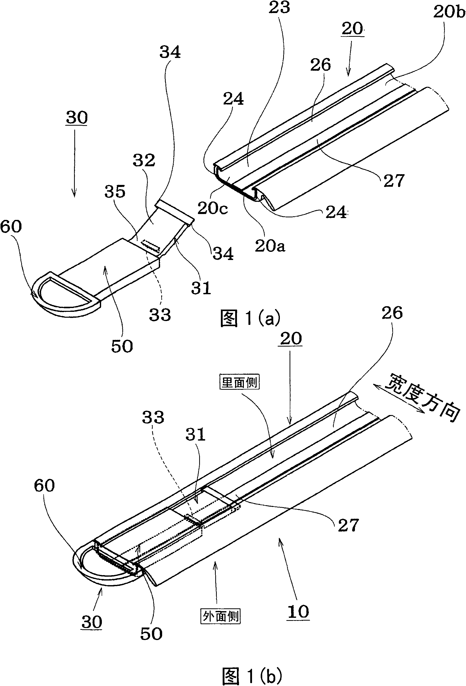
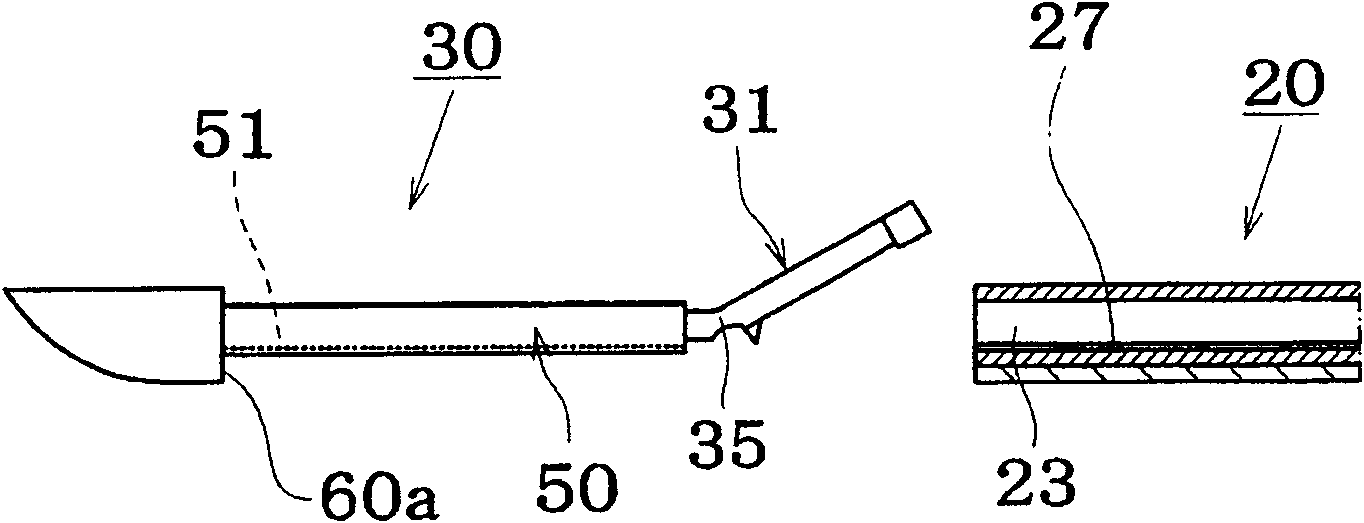
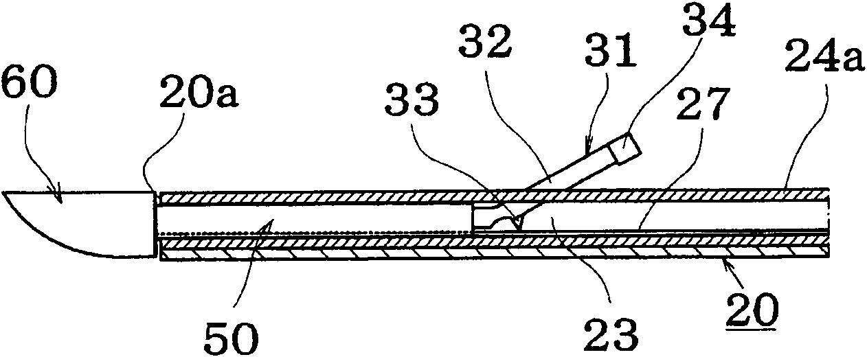
[0051] The automotive molding 10 of the present invention will be described with reference to the drawings.

[0052] Fig. 1(a) and Fig. 1(b) are explanatory diagrams of the molding 10 for automobiles, Fig. 1(a) shows the state before the end cap 30 is mounted on the molding main body 20, and Fig. 1(b) shows the end cap 30 The state of mounting on the molding body 20.

[0053] The molding main body 20 is in the shape of a C-shaped groove, and is manufactured by roll forming or the like.

[0054] The figures are drawn so that the inner surface 20b of the molding main body 20 faces upward and is viewed from the inner surface for easy understanding of the assembled state.

[0055] The end cap 30 is made of resin and is integrally formed by injection molding or the like, and has an insertion portion 50 , a rod portion 31 and a design portion 60 .

[0056] The insertion part 50 is inserted from the end opening 20c of the end 20a of the molding main body, and the rod part 31 has a ...


PUM


Abstract

The present invention provides a panel strip for a vehicle, wherein, the installation property is excellent when an end cap is inserted and assembled to the end of the panel strip. No clearance exists between the end cap and the end of the panel strip. The buckling force is high. The panel strip for the vehicle comprises a panel strip body and the end cap which is equipped to the end of the panelstrip body. The invention is characterized in that: the panel strip body is of a C groove shape with an inner surface side opening; turning-back parts in the inward direction are provided at both sides in the width direction; the end cap comprises an insertion part inserted to the bottom of the insertion strip body and an appearance part which covers the end surface of the insertion strip body; the insertion part is provided with a rod part which projects along the outer part and extends from the front end of the insertion through the inner side opening of the panel strip body when inserted into the panel strip body; the rod part is provided with fixing paws at two sides of the width direction; after the insertion part of the end cap is inserted into the end of the panel strip body, the front end of the rod part is rotated to the main body side of the panel strip, and the fixing paws are buckled to the turning-back parts of the panel strip body.

Description

technical field [0001] The invention relates to moldings for automobiles, in particular to an end cover installation structure at the end of the moldings. Background technique [0002] Roof moldings, side moldings, etc. of automobiles are equipped with end caps for the purpose of improving the appearance of the molding ends and preventing rust. [0003] Conventionally, the method of inserting the end cap into the end of the molding and adhesively fixing it is known, but there is a risk of contamination of the exterior surface due to exposure and whitening of the adhesive. [0004] In addition, before the adhesive is hardened, the end cap may fall off or the installation position may be misaligned, creating a gap between the molding and the molding. In addition, it is difficult to judge whether the bonding state is good from the outside, so there is a risk of sticking. The danger of accepting defective products. [0005] Japanese Patent Application Laid-Open No. 2007-1431 d...

Claims


Application Information

Patent Timeline
IPC IPC(8): B60R13/04
Inventor 竹好收沼元保幸
Owner KATAYAMA KOGYO CO LTD
Learn More