LED display module
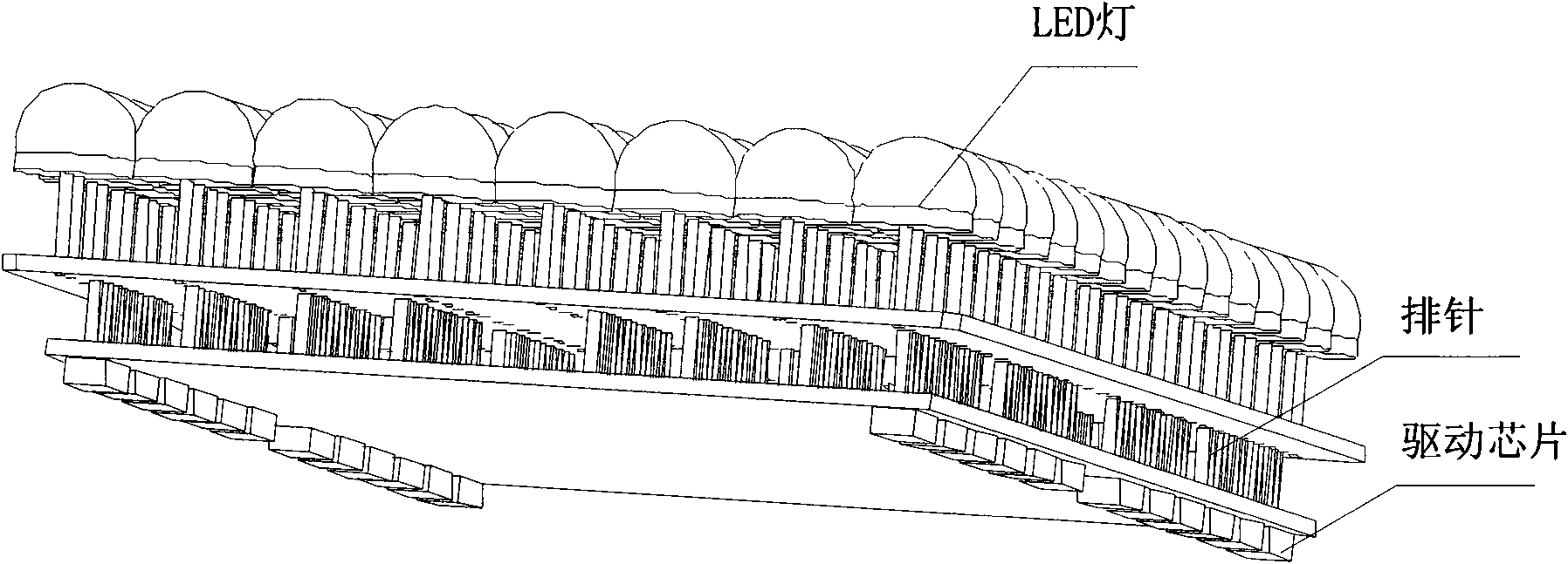
A technology of display module and LED light board, which is applied in the direction of instruments, identification devices, etc., can solve the inconvenience and flexibly handle the hardware connection mode between the control board and the LED light board, reduce the stability and reliability of signal transmission, and the structural tightness of the LED display module Major problems, to achieve the effect of reducing signal transmission connection points, reducing maintenance costs and difficulties, and improving stability and reliability
- Summary
- Abstract
- Description
- Claims
- Application Information
AI Technical Summary
Problems solved by technology
Method used
Image
Examples
Embodiment 1
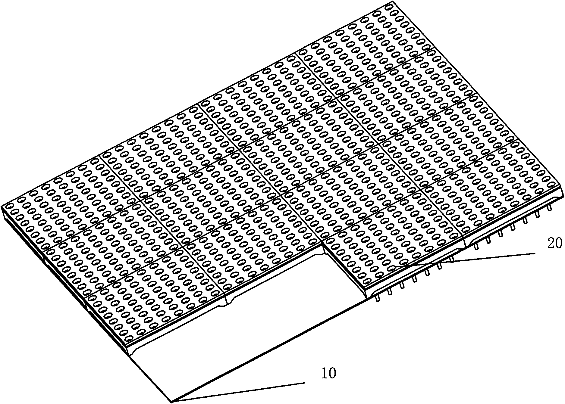
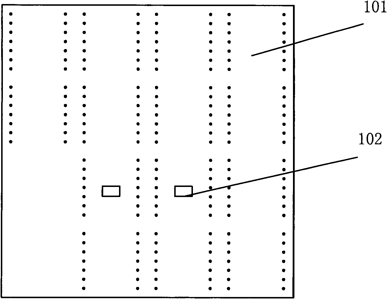
[0034] This embodiment provides an LED display module, refer to figure 2 , image 3 , Figure 4 and Figure 5 , including: a control board 10 and at least one LED lamp board 20, the control board 10 includes a first PCB board 101 and a control circuit 102, and the control circuit is used to send the LED lamp board to the LED lamp board through the first PCB board 101 20 provides control signals, the LED lamp board 20 includes a second PCB board 206, a column driver circuit 205 and LED pixel points 201, the LED pixel points 201 are placed on the front side of the second PCB board 206, and the column driver circuit The circuit is placed on the back of the second PCB board 206 to receive the control signal and drive the LED pixel 201 to emit light according to the control signal; thus, the present invention transfers the column drive circuit 205 to the LED lamp board Above, the position of the drive circuit on the original control board 10 can be hollowed out or no components...
Embodiment 2
[0037] On the basis of Embodiment 1, preferably, the LED light board described in this embodiment includes 64 LED pixels, and the 64 LED pixels form a square array of 8 by 8, such as Figure 4 The LED light board shown is composed of 64 identical LED pixel points 201 to form an 8 by 8 square array. Such a square array is convenient for installation and use.
[0038] Or, preferably, the above-mentioned LED pixels are composed of at least one blue LED, at least one red LED, and at least one green LED, and the above-mentioned LEDs can be LED lamps of any shape and any package structure as required.
[0039] Or, preferably, this embodiment integrates a sealed light-transmitting mask 202 on the LED lamp board 20. The lampshade is a sealed and waterproof structure, and contains 64 through holes on its surface. The mask is sealed and fixed on the second PCB board. Together, in this way, each through hole accommodates an LED pixel, injects transparent material into the through hole, a...
Embodiment 3
[0042] On the basis of the above-mentioned embodiments, preferably, in this embodiment, the sealing light-transmitting mask 203 is extended to form a support portion 203 along the normal direction of the back of the second PCB board 206, that is, the direction perpendicular to the second PCB board , the supporting part 203 is used to support the LED lamp board 20 when the LED lamp board 20 is installed on the control board 10, so that the LED lamp board 20 will not shake left and right, up and down.
[0043] Furthermore, in a preferred example, four supporting parts 203 can be set, and the above-mentioned supporting parts 203 are arranged on the four legs of the sealed light-transmitting mask 202, such as Figure 4 As shown in , at the same time, the above-mentioned support part 203 can be higher than the back of the above-mentioned sealed light-transmitting mask 202, so that after installation, a gap can be left between the LED lamp board 20 and the control board 10 to facilit...
PUM
 Abstract
Description
Claims
Application Information
 - Generate Ideas
- Intellectual Property
- Life Sciences
- Materials
- Tech Scout
- Unparalleled Data Quality
- Higher Quality Content
- 60% Fewer Hallucinations
Browse by: Latest US Patents, China's latest patents, Technical Efficacy Thesaurus, Application Domain, Technology Topic, Popular Technical Reports.
© 2025 PatSnap. All rights reserved.Legal|Privacy policy|Modern Slavery Act Transparency Statement|Sitemap|About US| Contact US: help@patsnap.com


