Combined photographic cantilever pan tilt

A combined and cantilever technology, applied in the field of photographic equipment, can solve the problems of inconvenient carrying, uncompact structure of the pan/tilt, and large space occupation

Active Publication Date: 2010-02-03
江西百诺旅行箱包有限公司
View PDF1 Cites 22 Cited by
  • Summary
  • Abstract
  • Description
  • Claims
  • Application Information

AI Technical Summary

Problems solved by technology

Due to the large size of the main bracket and the cantilever of the cantilever head, especially the main bracket is a whole and cannot be disassembled, the structure of the head is not compact, the shape is not standardized, it takes up a lot of space when it is carried or packed, and it is inconvenient to carry. high packaging cost

Method used


Image

  • Combined photographic cantilever pan tilt
  • Combined photographic cantilever pan tilt
  • Combined photographic cantilever pan tilt

Examples


Embodiment Construction

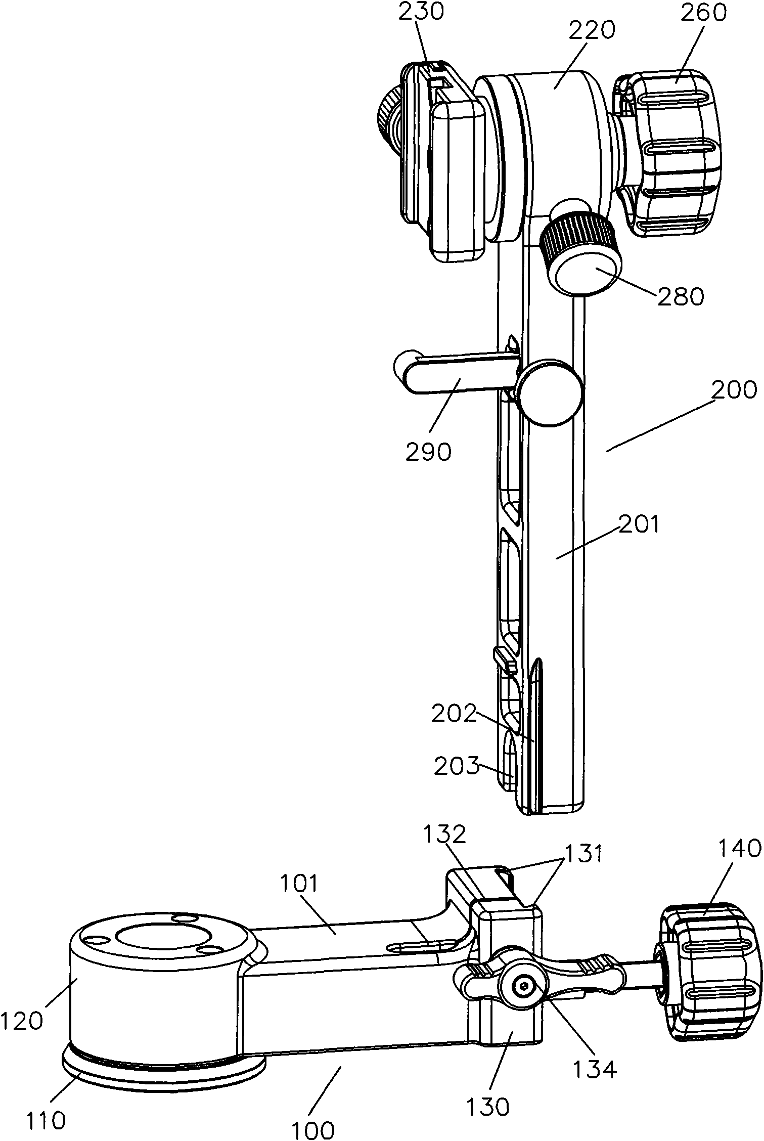
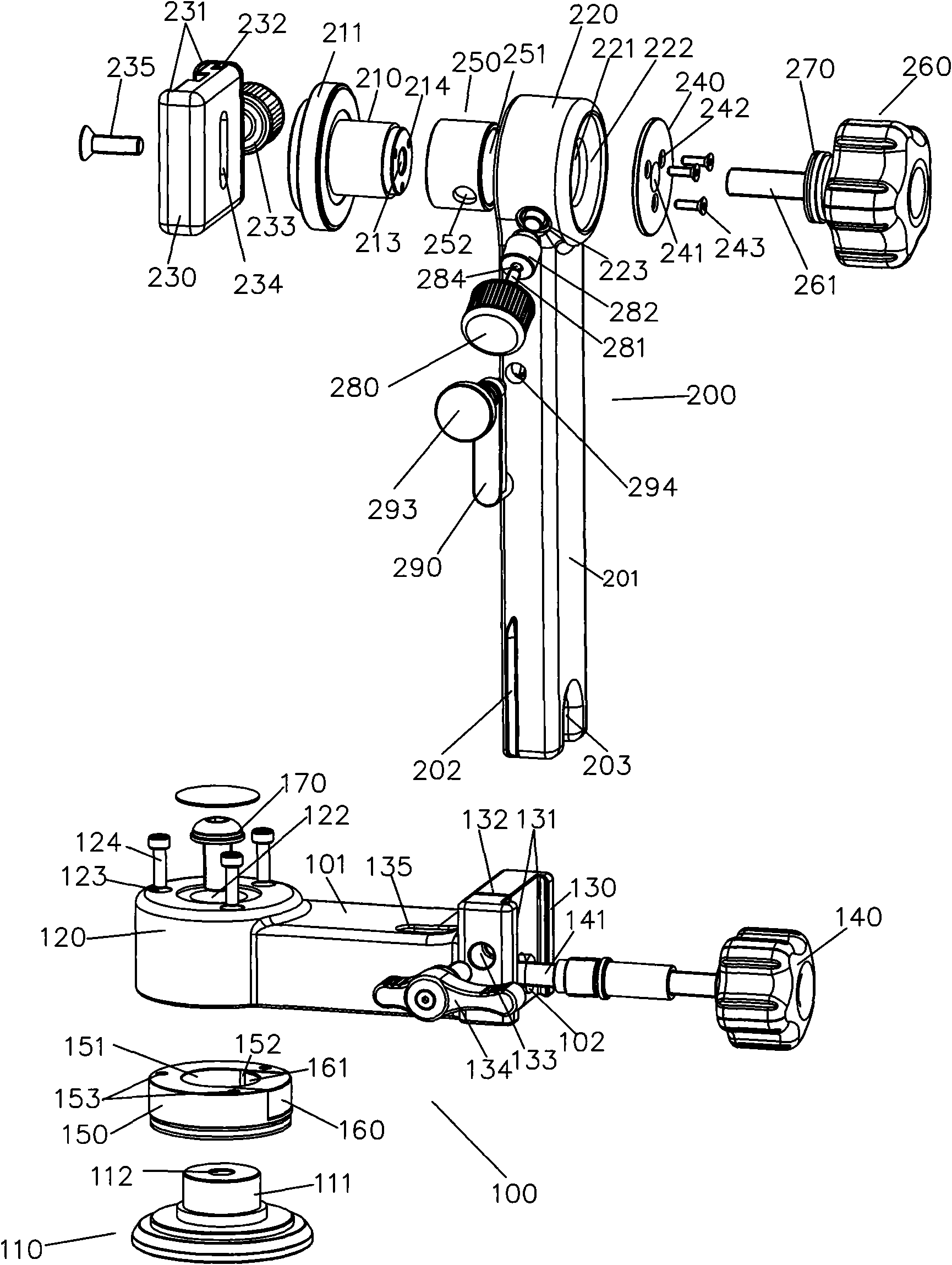
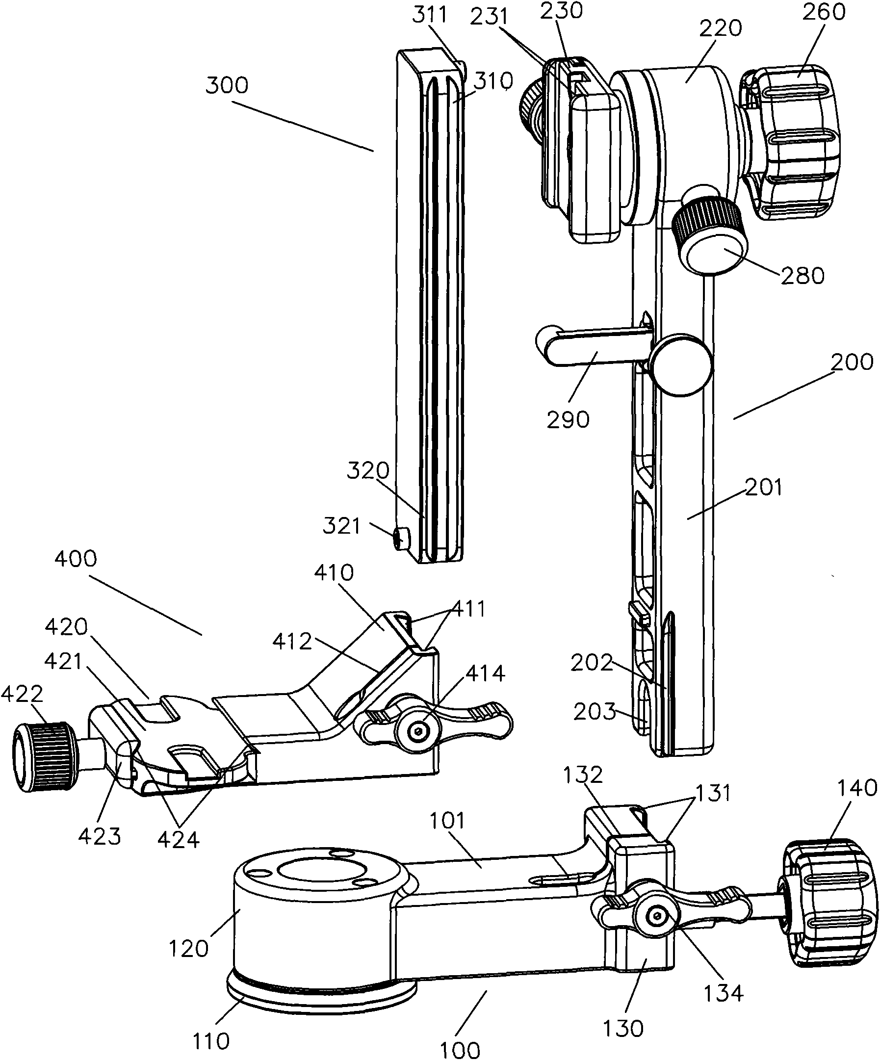
[0025] like figure 1 , figure 2 , Figure 4 As shown, the present invention includes a horizontal support assembly 100 and a vertical support assembly 200 with a free end, and the horizontal rotating support assembly 100 and the vertical support assembly 200 can be separated and combined into an L-shaped support through a flexible connection; wherein:

[0026] The free end of the horizontal support assembly 100 has a base 110 and a vertical sleeve 120 axially movably connected with the base 110, and a locking device is provided at the movably connected place. The structure of its movable connection and the locking device at the movable connection can adopt the existing technology in this technical field, such as the movable connection can be the rotating and matching mode of the rotating shaft and the sleeve, the general hinged joint mode or the pivotal joint mode, etc., as long as it can reach vertical The function that the axle sleeve 120 realizes 360° rotation on the bas...


PUM


Abstract

The invention discloses a combined photographic cantilever pan tilt. The combined photographic cantilever pan tilt comprises a horizontal rotary bracket assembly and a vertical bracket assembly whichcan be separated and also can be combined into an L-shape bracket, wherein, a free end of the horizontal rotary bracket assembly is provided with a base and a vertical shaft sleeve which is axially and movably connected with the base, and a movable connecting part is provided with a locking apparatus; the horizontal rotary bracket assembly and the vertical bracket assembly are movably connected with each other and a movable connecting part is provided with a locking apparatus; and main parts of the various assemblies are rod-shaped. The pan tilt also can comprise a rotating arm assembly and acamera quick clamp assembly. Compared with the prior art, the combined photographic cantilever pan tilt is provided with various assemblies which are movably connected with each other, and use flexibility of the pan tilt can be improved and various parts can be detached from each other without tools by movably connected structures. As the assembly of each part has compact structure and regular shape, the various detached assemblies take up small space and have low packaging cost.

Description

technical field [0001] The invention relates to photographic equipment, in particular to a combined photographic cantilever platform. Background technique [0002] Most of the cantilever platforms in the prior art are monolithic structures. The publication number is CN200956085, a Chinese patent disclosed on October 3, 2007, which discloses a cantilever platform for cameras, including a base, a cantilever main bracket, an L-shaped cantilever platform and a quick-release plate base. The base is vertical The direction axis is connected to the cantilever main bracket, and is fastened with a vertical knob, and a mounting screw hole is provided at the bottom; one end of the L-shaped cantilever platform is horizontally connected to the cantilever main bracket, And it is fastened with a horizontal knob, and the other end is equipped with a quick release plate base. The cloud platform of the above structure is not a combined type, even if it can be disassembled, it is also designe...

Claims


Application Information

Patent Timeline
Patent Type & Authority Applications(China)
IPC IPC(8): G03B17/56F16M11/00
Inventor 刘昊
Owner 江西百诺旅行箱包有限公司
Why Eureka
Try Eureka