Triaxial acceleration sensor

An acceleration sensor, axis technology, applied in the measurement of acceleration, multi-dimensional acceleration measurement, speed/acceleration/shock measurement, etc., can solve problems such as high space requirements, and achieve the effect of suppressing zero-point deviation and compact structure

Inactive Publication Date: 2010-02-03
ROBERT BOSCH GMBH
View PDF0 Cites 13 Cited by
  • Summary
  • Abstract
  • Description
  • Claims
  • Application Information

AI Technical Summary

Problems solved by technology

This results in high space requirements and relatively large acceleration sensors

Method used


Image

  • Triaxial acceleration sensor
  • Triaxial acceleration sensor

Examples


Embodiment Construction

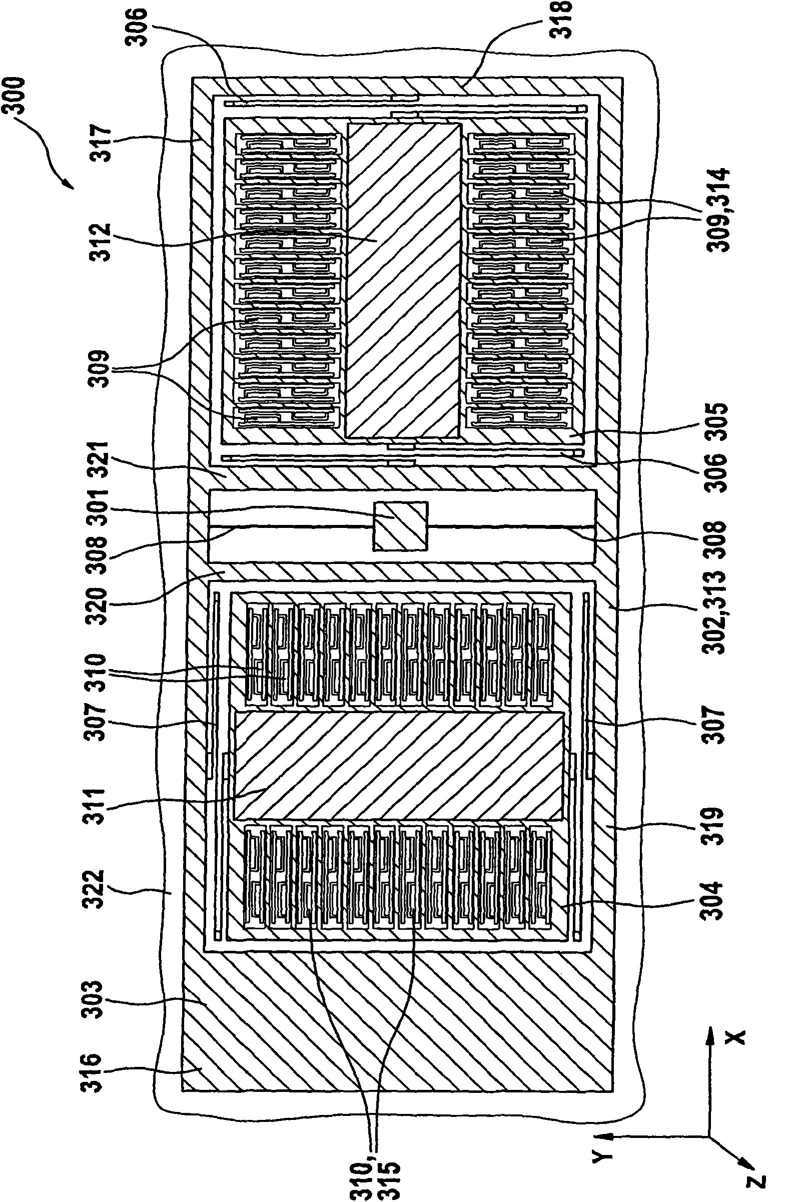
[0016] figure 1 A schematic diagram of a first embodiment of an acceleration sensor 300 is shown, which is arranged on the z-axis above the surface of a substrate 322 lying in the x-y plane. The acceleration sensor 300 is suitable for detecting accelerations in all three spatial directions x, y, z. Acceleration sensor 300 is made of, for example, a silicon substrate as a micromechanical component.

[0017] The acceleration sensor 300 includes an outer frame 313 arranged in an x-y plane. The outer frame 313 has a rectangular basic shape. The outer edge of the outer frame 313 is composed of a first frame part 316 , a second frame part 317 , a third frame part 318 and a fourth frame part 319 . The first frame member 316 and the third frame member 318 are oriented parallel to the y-axis. The second frame part 317 and the fourth frame part 319 are oriented parallel to the x-axis. The area enclosed by the first frame member 316, the second frame member 317, the third frame memb...


PUM


Abstract

The present invention relates to an acceleration sensor, especially to a triaxial acceleration sensor, which includes a substrate and a first mass element, which is connected to the substrate in sucha way that the first mass element is rotatable about an axis, the first mass element being connected to a second mass element in such a way that the second mass element is movable along a first direction parallel to the axis, and the first mass element being connected to a third mass element in such a way that the third mass element is movable along a second direction perpendicular to the axis.

Description

technical field [0001] The invention relates to an acceleration sensor with a mass arranged above a base plane. Background technique [0002] For applications in entertainment and automotive electronics, a three-axis acceleration sensor, especially a micromechanical three-axis acceleration sensor is desired. Here, it is desirable for the acceleration sensor to have a construction that is as compact as possible. [0003] The basic principle of a micromechanical acceleration sensor is that a seismic mass is mounted on a substrate movably relative to a fixed electrode by means of a suspension. The vibrating mass and the stationary electrodes form one or more capacitors. The displacement of the seismic mass caused by the acceleration acting on the micromechanical acceleration sensor results in a change in the capacitance of these capacitors, which can be detected and used as a measure for the magnitude of the acting acceleration. In order to avoid zero point deviations, the c...

Claims


Application Information

Patent Timeline
Patent Type & Authority Applications(China)
IPC IPC(8): G01P15/18B81B7/02
CPCG01P2015/0814G01P15/18G01P15/125G01P2015/0831
Inventor J·克拉森L·特夫耶
Owner ROBERT BOSCH GMBH
Why Eureka
Try Eureka