Light emitting diode module, backlight source and display device

A technology of light-emitting diodes and backlights, which is applied in the fields of light-emitting diode modules, backlights, and display devices. It can solve problems such as inaccurate positioning of LEDs, weakened close contact between LEDs and light guide plates, and waste of light sources. Point phenomenon, good connection stability

Inactive Publication Date: 2010-02-03
AU OPTRONICS (SUZHOU) CORP LTD +1
View PDF0 Cites 5 Cited by
  • Summary
  • Abstract
  • Description
  • Claims
  • Application Information

AI Technical Summary

Problems solved by technology

In addition, an increase in the distance between the light guide plate and the LEDs will correspondingly increase the size of the LCD device
[0004] The existing method to improve the above problem is to fix the LED module on the light guide plate by materials such as double-sided tape, but the tape will affect its function as a fixation when it is subjected to cold and heat shock or the external environment deteriorates, and the tape Losing the fixing effect under external influence will cause inaccurate positioning of the LED, the close contact between the LED and the light guide plate may be weakened, and the above-mentioned white spot phenomenon will appear, and even light leakage and waste of light source will occur.

Method used


Image

  • Light emitting diode module, backlight source and display device
  • Light emitting diode module, backlight source and display device
  • Light emitting diode module, backlight source and display device

Examples


Embodiment Construction

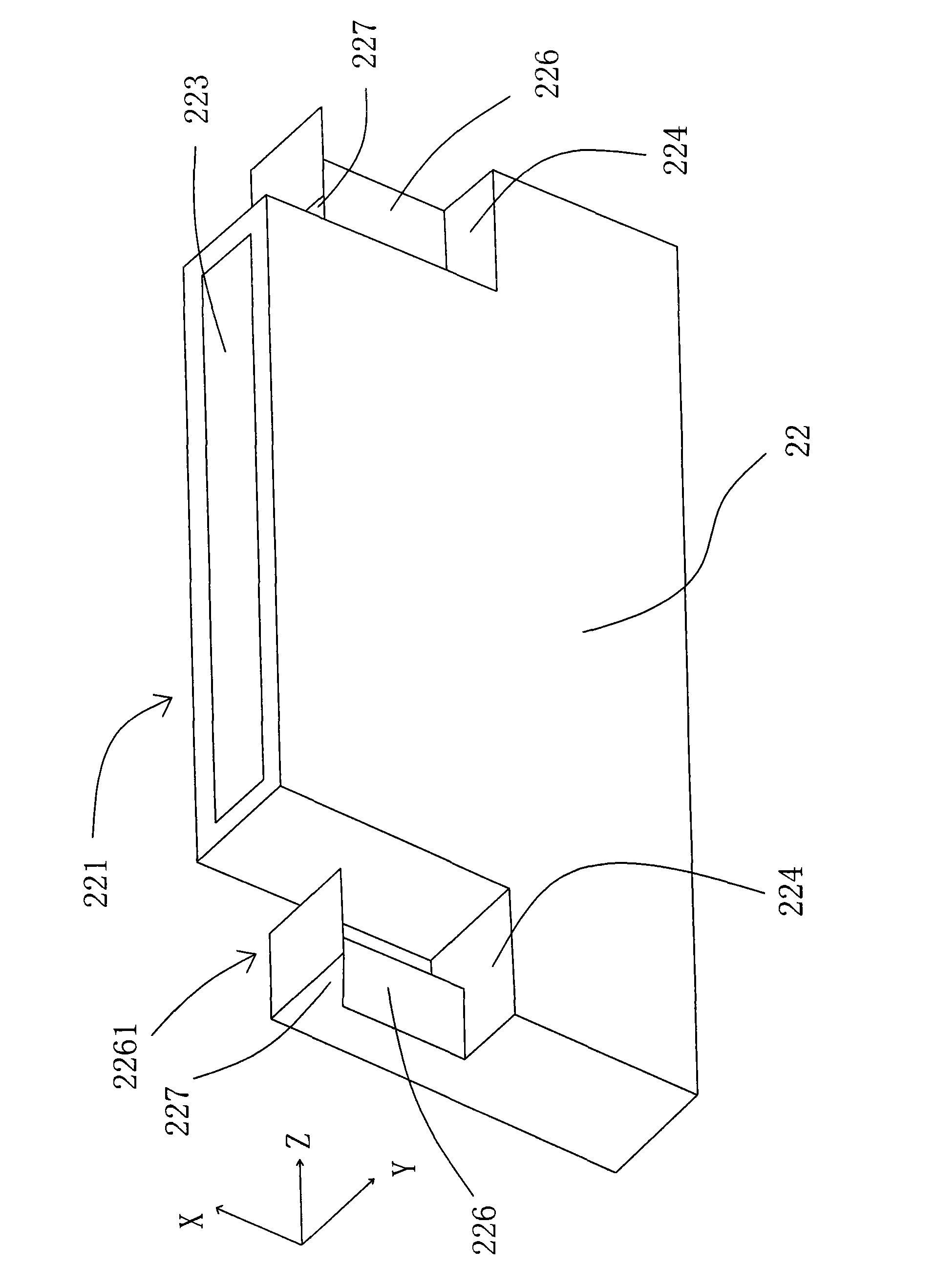
[0021] Please refer to figure 2 , figure 2 A schematic bottom perspective view of the LED module according to the first embodiment of the present invention is shown. The light-emitting diode module 22 of this embodiment includes a light-emitting surface 223 (parallel to the YZ plane in the figure) on its light-emitting side 221; two bumps 226 located on the light-emitting side 221 and on both sides of the light-emitting surface 223; Two positioning blocks 227 respectively located on the two protrusions 226 and pointing to the first side direction of the LED module 22 (ie, the Y-axis direction in the figure), the first side direction is parallel to the light-emitting surface 223 and perpendicular to the direction of the line connecting the two bumps (that is, the direction of the Z axis in the figure).

[0022] In this embodiment, the light-emitting diode module 22 has grooves 224 on both sides of the light-emitting surface 223, the protrusions 226 are placed in the grooves...


PUM


Abstract

The invention relates to a light emitting diode module, a backlight source and a display device, belonging to the field of light emitting diode modules with connection structures as well as backlightsources and display devices using same. The invention aims at providing a light emitting diode module which comprises a light emitting surface positioned at a light emitting side of the light emittingdiode module, two bumps which are positioned at the light emitting side and respectively arranged at two sides of the light emitting surface, and two positioning blocks which are respectively positioned on the two bumps and point to a first side direction of the light emitting diode module. The first side direction is parallel to the light emitting surface and vertical to the connection line of the two bumps.

Description

【Technical field】 [0001] The invention relates to a light-emitting diode module, a backlight source and a display device, in particular to a light-emitting diode module with a connection structure and a backlight source and a display device using the light-emitting diode module. 【Background technique】 [0002] Liquid crystal display (LCD) devices have been widely used in various industrial fields due to their light weight, compactness, and low power consumption. Since the liquid crystal display panel of the LCD device is not self-illuminating, the LCD device requires a backlight for providing light to the liquid crystal display panel. [0003] Since light-emitting diodes (LEDs) can achieve lower power consumption, better resistance to external shocks, wider application in small and compact devices, longer life, and faster switching speeds than cold-cathode fluorescent lamps, Can be used as a light source in a backlight. like figure 1 What is shown is a schematic diagram o...

Claims


Application Information

Patent Timeline
Patent Type & Authority Applications(China)
IPC IPC(8): F21S2/00F21V8/00F21V19/00G02F1/13357G02F1/1333F21Y101/02F21K9/23F21Y115/10
Inventor 张功磊林昆标
Owner AU OPTRONICS (SUZHOU) CORP LTD
Why Eureka
Try Eureka