Centrifugal clutching transmission mechanism

A clutch transmission and centrifugal technology, applied in the field of transmission mechanism, can solve the problems of difficult processing, increased collision times, complex mechanism structure, etc., and achieve the effects of convenient installation, maintenance and disassembly, increased collision area, and simple mechanism structure.

Inactive Publication Date: 2010-02-03
钱贤峰
View PDF0 Cites 0 Cited by
  • Summary
  • Abstract
  • Description
  • Claims
  • Application Information

AI Technical Summary

Problems solved by technology

[0004] 1. The structure of the mechanism is complex, and it is inconvenient to install, maintain and disassemble, especially some parts such as "L"-shaped levers, limit pins, ratchets, and pawls. Due to their functional requirements, their special structures and processing difficulties are determined. Big
[0005] 2. Since the lever used for centrifugal movement overcomes the force of the tension spring, and the pawl and the ratchet are clutched through the limit pin, in the working process, the performance is unstable, the energy consumption is high, the transmission torque is small, and the working efficiency is low.
[0006] 3. Since the extension spring is suspended in the air and installed on the lever and pawl seat, coupled with the influence of its elastic fatigue, after a period of working, the limit pin cannot work reliably, and its life is short, which affects the normal use of the electric wrench
[0007] 4. When the ratchet and the ratchet collide and collide with the ratchet, the contact area between the ratchet and the ratchet is small, and the ratchet is easy to wear during multiple clutch collisions, resulting in a smaller rotation range of the ratchet and an increase in the number of collisions. The efficiency is low, and in severe cases, it may even knock off the bumped part on the ratchet, making the electric wrench unable to work normally

Method used


Image

  • Centrifugal clutching transmission mechanism
  • Centrifugal clutching transmission mechanism

Examples


Embodiment Construction

[0019] The present invention will be further described below in conjunction with the accompanying drawings and specific embodiments.

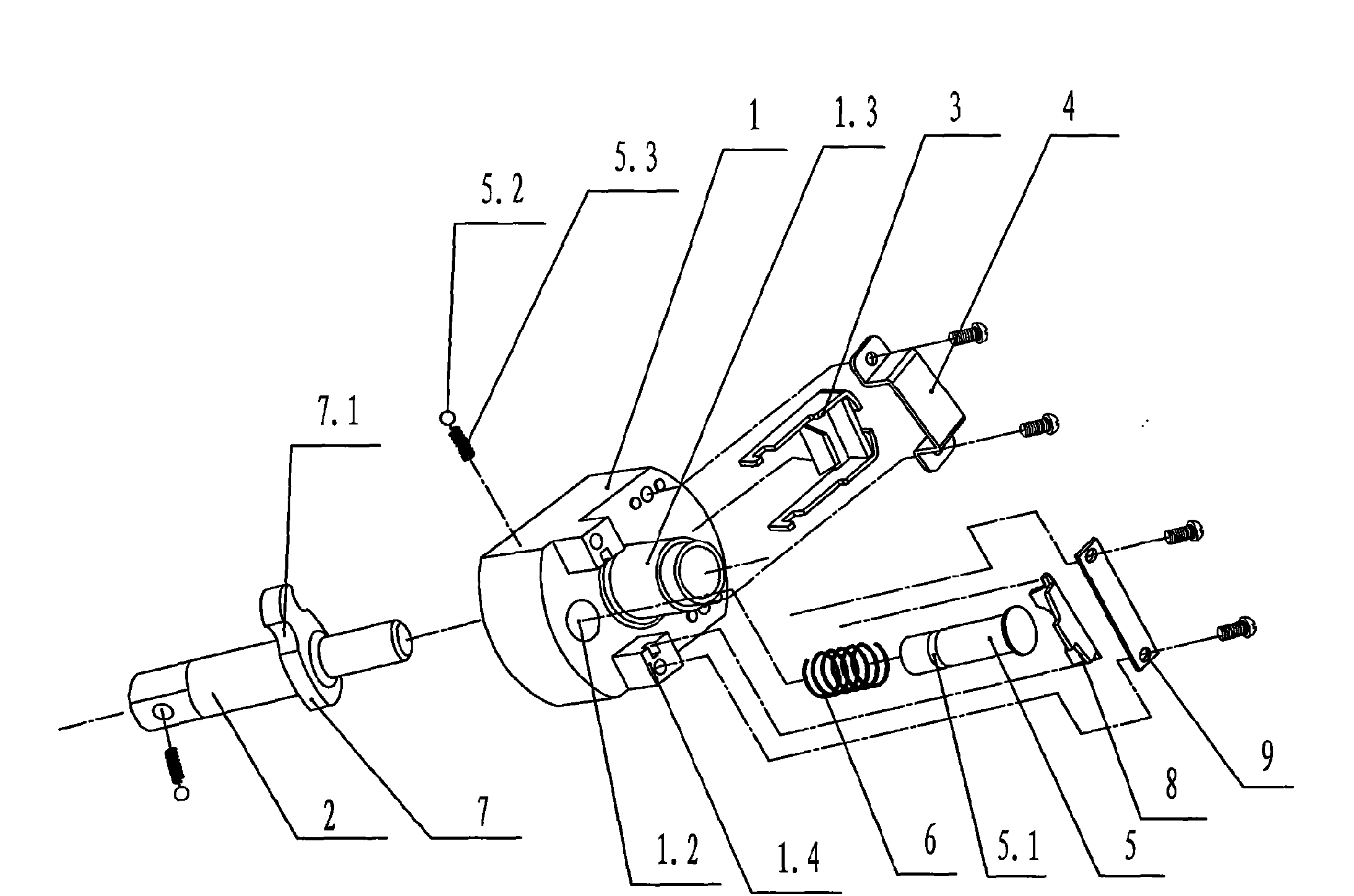
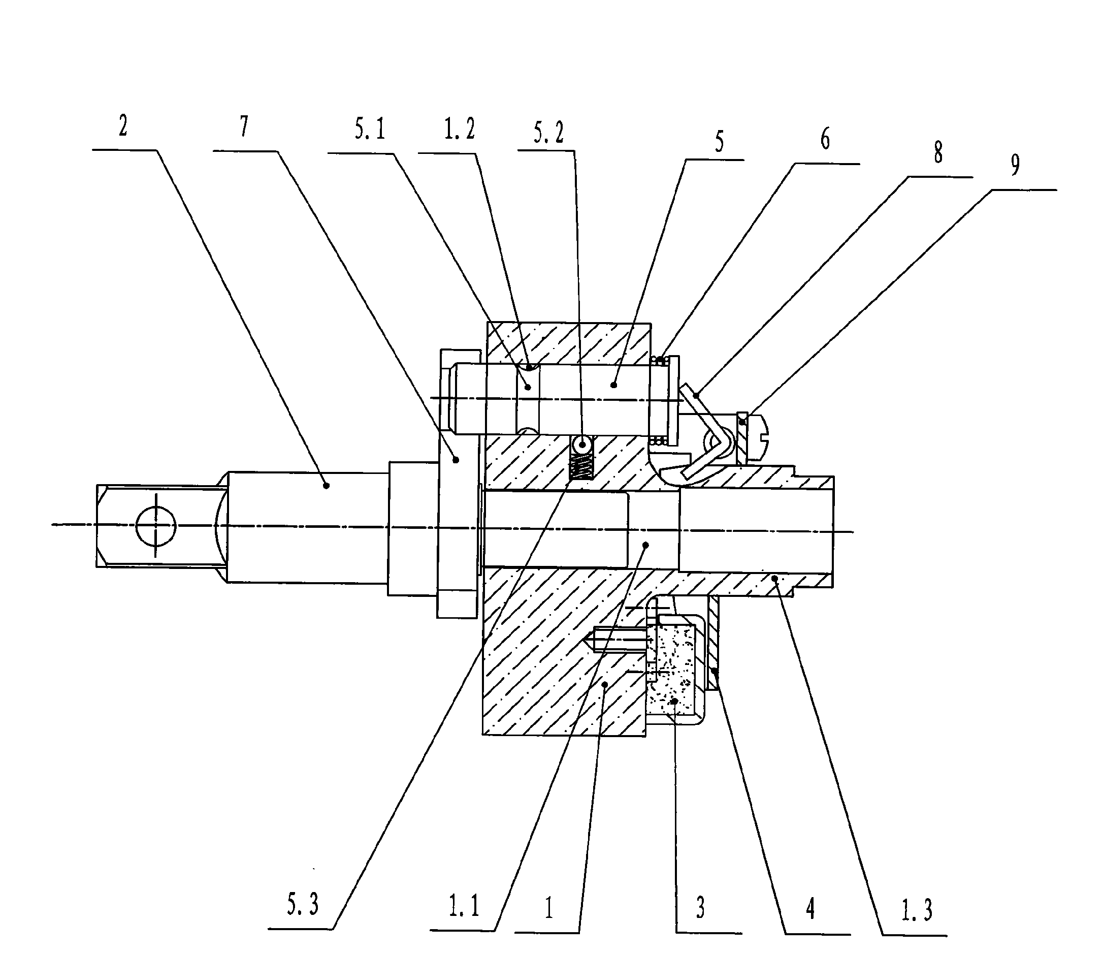
[0020] Such as figure 1 , figure 2 As shown, the centrifugal clutch transmission mechanism of the present invention includes a ratchet 1, an output eccentric shaft 2 arranged at the rear end of the ratchet 1 and covered with a sleeve; the output eccentric shaft 2 is rotatably fitted in the central hole 1.1 of the ratchet 1; The front end of the ratchet 1 is provided with a shaft sleeve 1.3 which is integrated and connected to the motor; the central hole 1.1 of the ratchet 1 is coaxial with the shaft sleeve 1.3; Plate assembly; the pull plate assembly includes a pull plate 3 and a pull plate fixing seat 4; the pull plate 3 is set on the shaft sleeve 1.3, and the front end of the pull plate 3 close to the shaft sleeve 1.3 has a bent edge, and the rear end is embedded There is a pull plate counterweight, and a pull plate fixing seat 4 is provid...


PUM


Abstract

The invention discloses a centrifugal clutching transmission mechanism which comprises a ratchet wheel (1) and an output eccentric shaft (2) which is arranged at the rear end of the ratchet wheel (1)and rotationally matched with a central hole (1.1) of the ratchet wheel (1), wherein the front end face of the ratchet wheel (1) is provided with a shaft sleeve (1.3) which is fixed into a whole withthe ratchet wheel (1) and coaxial with the central hole (1.1) of the ratchet wheel (1); the front end face of the ratchet wheel (1) is also provided with longitudinally distributed pulling plate components and transversely distributed pressing plate components and a guide post (5) which is matched in an eccentric hole (1.2) of a flywheel (1) in a sliding way, wherein the longitudinally distributedpulling plate components and the transversely distributed pressing plate components perform centrifugal motions; a return spring (6) is sleeved on the guide post (5); the output eccentric shaft (2) is provided with a connection block (7) which is fixed into a whole with the output eccentric shaft (2) and provided with symmetrical grooves (7.1); the pulling plate components and the pressing platecomponents are mutually buckled; the pressing plate components are abutted against the end face of the head part of the guide post (5); and the outer cylindrical surface of the tail part of the guidepost (5) is abutted against one corresponding groove (7.1) according to the steering of a motor. The invention has stable performance, less energy consumption, high working efficiency, long service life and difficult damage.

Description

technical field [0001] The invention relates to a transmission mechanism, in particular to a centrifugal clutch transmission mechanism used on an electric wrench. Background technique [0002] The centrifugal clutch transmission mechanism of the centrifugal electric wrench generally adopts a pawl clutch mechanism, which mainly includes a pawl, a ratchet wheel, a pawl seat, and an "L"-shaped lever. In the ratchet seat, the ratchet wheel is located in the hollow part of the ratchet seat and is offset against the pawl. The middle part of the lever is rotatably fixed on the boss on the rear wall of the ratchet seat through a pin shaft. One end of the lever is connected with one end of the tension spring. The other end of the extension spring is fixed on the pawl seat, the other end of the lever is connected with the limit pin, the limit pin is slidably arranged in the corresponding through hole on the rear wall of the pawl seat, and the limit pin extends into the pawl seat just...

Claims


Application Information

Patent Timeline
Patent Type & Authority Applications(China)
IPC IPC(8): B25B23/00B25B21/00F16D43/04
Inventor 钱贤峰
Owner 钱贤峰
Why Eureka
Try Eureka