
Active AP scan method for in 802.11 wireless local area network

A wireless local area network, active technology, applied in the field of communication, can solve the problem of long AP scanning time during MAC switching, and achieve the effect of realizing resource utilization and improving operating efficiency

Inactive Publication Date: 2010-01-27
SHANGHAI JIAO TONG UNIV
View PDF0 Cites 24 Cited by
  • Summary
  • Abstract
  • Description
  • Claims
  • Application Information

AI Technical Summary

Problems solved by technology

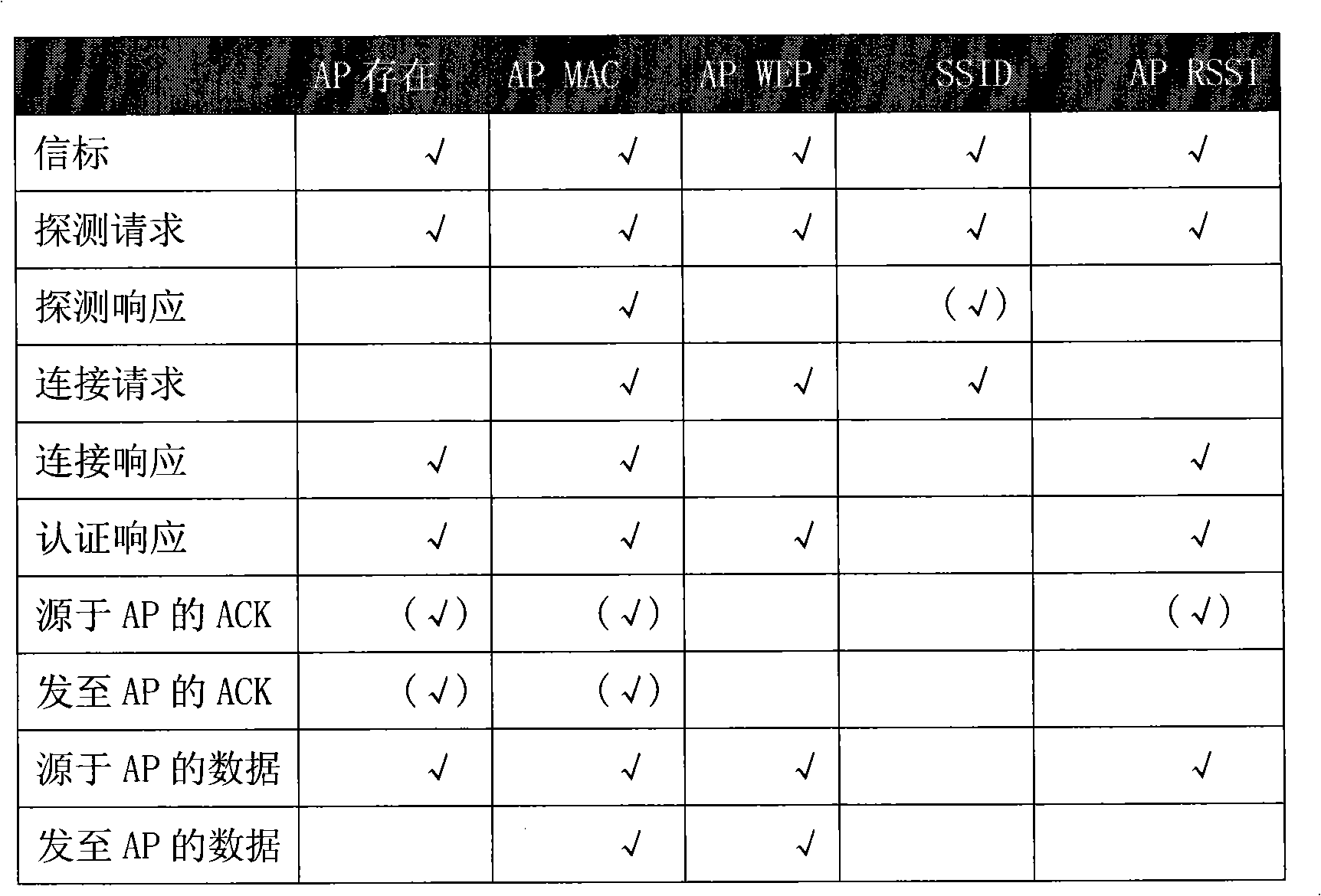
The present invention solves the problem of too long AP scanning time during MAC switching in the existing 802.11 wireless local area network protocol, overcomes the defects that the existing fast AP scanning method needs to change the network protocol, etc., only needs to modify the client program, and makes full use of the non-destructive capabilities of the MS. Switch time and various useful MAC frames on the channel, enabling fast and efficient AP scanning

Method used


Image

  • Active AP scan method for in 802.11 wireless local area network
  • Active AP scan method for in 802.11 wireless local area network
  • Active AP scan method for in 802.11 wireless local area network

Examples


Embodiment 1

[0032] In this embodiment, first send a detection request, then the MS monitors the channel, sniffs and scans for a specified time, intercepts all heard MAC frames for analysis, obtains relevant information of adjacent APs and records them in the MS's AP information database, and completes the initiative at the same time. scanning. This embodiment shows the number of APs scanned by traditional active scanning and this method under different scanning time lengths. We performed 10 times for each scanning time length and took the average, which is listed in Table 2.

[0033] Table 2 The average number of captured APs under different scan durations

[0034]

[0035] Table 2 shows that the number of APs scanned by this method is close to twice that of traditional active scanning, which has a very large advantage.

Embodiment 2

[0037] In this embodiment, the selected maximum scan time is 30ms, 15ms and 6ms. In the implementation process, first send a probe request, then start sniffing and scanning for 200ms, analyze all the monitored MAC frames, and obtain the relevant information of neighboring APs, but only intercept the previous Nms (N=30, 15 or 6) The response is recorded as valid data into the local database. It is then compared with all received responses to obtain the ratio in the first row of Table 3. The second row indicates the probability of finding the AP with the strongest signal. Each time period was implemented three times, and the average results are listed in Table 3.

[0038] Table 3 Performance of optimal detection and sniffing at different times

[0039]

[0040] Table 3 shows that when optimizing the probe response, if the interception time is set to 30 ms, 15 ms and 6 ms respectively, enough APs with good signals can be scanned.


PUM


Abstract

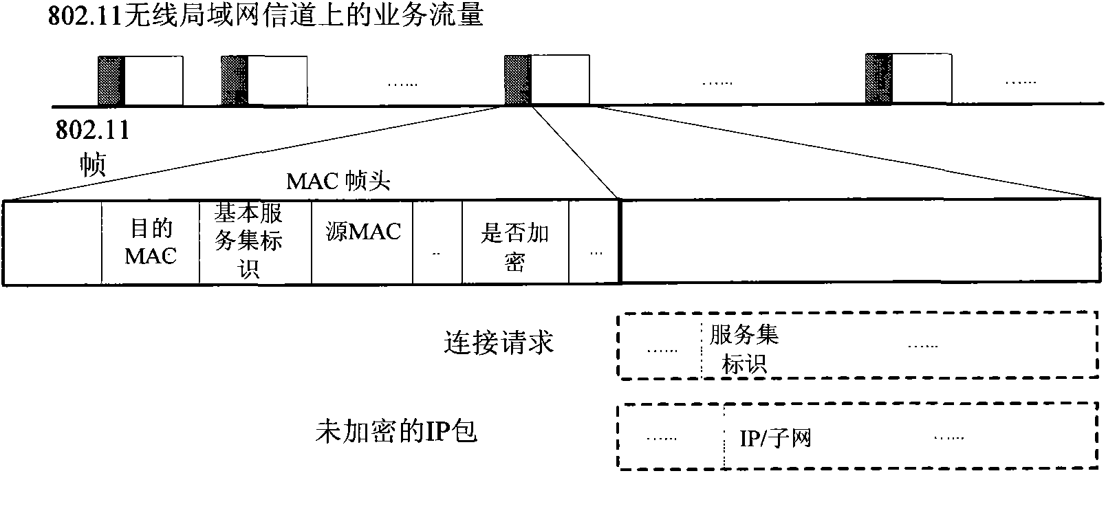
The invention relates to an active AP scan method in an 802.11 wireless local area network, belonging to the technical field of communications. The method comprises the following steps: sending out an exploring request MAC frame; carrying out sniffing scanning before receiving exploring responses of the AP so as to acquire other useful MAC frames, and analyzing all MAC frame header information to acquire related information of the adjacent AP; optimizing the exploring responses, and intercepting data within former 30ms as effective data; updating an AP database by adopting the data acquired in the step 2; repeating all steps to scan continuously if the AP that is suitable for switching is not explored, or finishing the scanning. The invention solves the defects that the scanning time of the AP is overlong during the MAC switching in the prior 802.11 wireless local area network, overcomes the shortages that a network protocol needs to be changed in the prior rapid AP scan method, and the like, just needs to correct client-terminal programs, fully utilizes the non-switching time of an MS and various useful MAC frames in the air, and achieves rapid and effective AP scanning.

Description

technical field [0001] The invention relates to a method in the technical field of communication, in particular to a method for active AP scanning in an 802.11 wireless local area network. Background technique [0002] The communication radius of an AP in an 802.11 WLAN is generally less than 100 meters. In order to cover a relatively large area, a large number of APs must be deployed. In many cases, because a wireless connection client needs to move, when the user gradually leaves the range of a certain AP, his (her) mobile terminal (MS) should switch to another AP within a short time . Handover directly determines the user's communication quality of service (QoS), because if the handover cannot be completed or the handover delay is too long, the user's communication, especially some sessions with strong real-time nature, will be affected or even completely interrupted. In reality, MAC switching will introduce a second-level delay, which is mainly caused by the full-freq...

Claims


Application Information

Patent Timeline
IPC IPC(8): H04W36/08H04W48/16
Inventor 徐昌庆滕劲刘大鹏查希周洲
Owner SHANGHAI JIAO TONG UNIV
Learn More