
Motor rotor structure and manufacturing method thereof

A technology of motor stator and manufacturing method, which is applied in the field of structure and stator manufacturing, and can solve the problems of high cost, high price, and inferior performance to silicon steel sheets, etc.

Inactive Publication Date: 2010-01-27
HOFO AUTOMATION CO LTD
View PDF1 Cites 2 Cited by
  • Summary
  • Abstract
  • Description
  • Claims
  • Application Information

AI Technical Summary

Problems solved by technology

However, in order to connect and combine the silicon steel sheets, it is necessary to weld the silicon steel sheets with a laser, or to punch out concave and convex points on each silicon steel sheet to connect with each other. Laser welding requires the purchase of a laser machine, which is expensive. If the silicon steel sheet is connected, it will affect the electromagnetic field on the silicon steel sheet, causing magnetic loss and eddy current loss
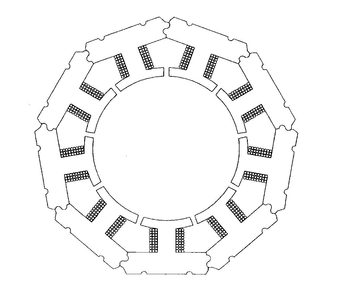
[0007] In addition, China Taiwan Invention Patent Announcement No. I288518 is an improved patent for traditional stators, such as image 3 Its planar structure diagram shows that the patented stator is composed of nine groups of I-shaped single magnetic poles surrounded by a circle. The I-shaped single magnetic pole is an iron core made of integrally formed shape, not composed of silicon steel sheets, so it can solve the problem of laser The disadvantage of welding or clamping the silicon steel sheet with concave and convex points, but the cost of the iron core is much higher than that of the silicon steel sheet, and the performance is not as good as the silicon steel sheet
[0008] The above-mentioned existing motor stator has advantages regardless of its structure or material, but it also has shortcomings to be overcome. Therefore, the inventor of this case proposes a structure and manufacturing method of a motor stator composed of silicon steel sheets, which can overcome the existing motor stator structure and process disadvantages while retaining all the advantages

Method used


Image

  • Motor rotor structure and manufacturing method thereof
  • Motor rotor structure and manufacturing method thereof
  • Motor rotor structure and manufacturing method thereof

Examples


Embodiment Construction

[0026] In order to further illustrate the technology, means and effects that the present invention takes to achieve the predetermined purpose, please refer to the following detailed description and accompanying drawings of the present invention. It is believed that the purpose, characteristics and characteristics of the present invention can be obtained from this in-depth and specific Understand, however, the provided drawings are only for reference and illustration, and are not intended to limit the present invention.

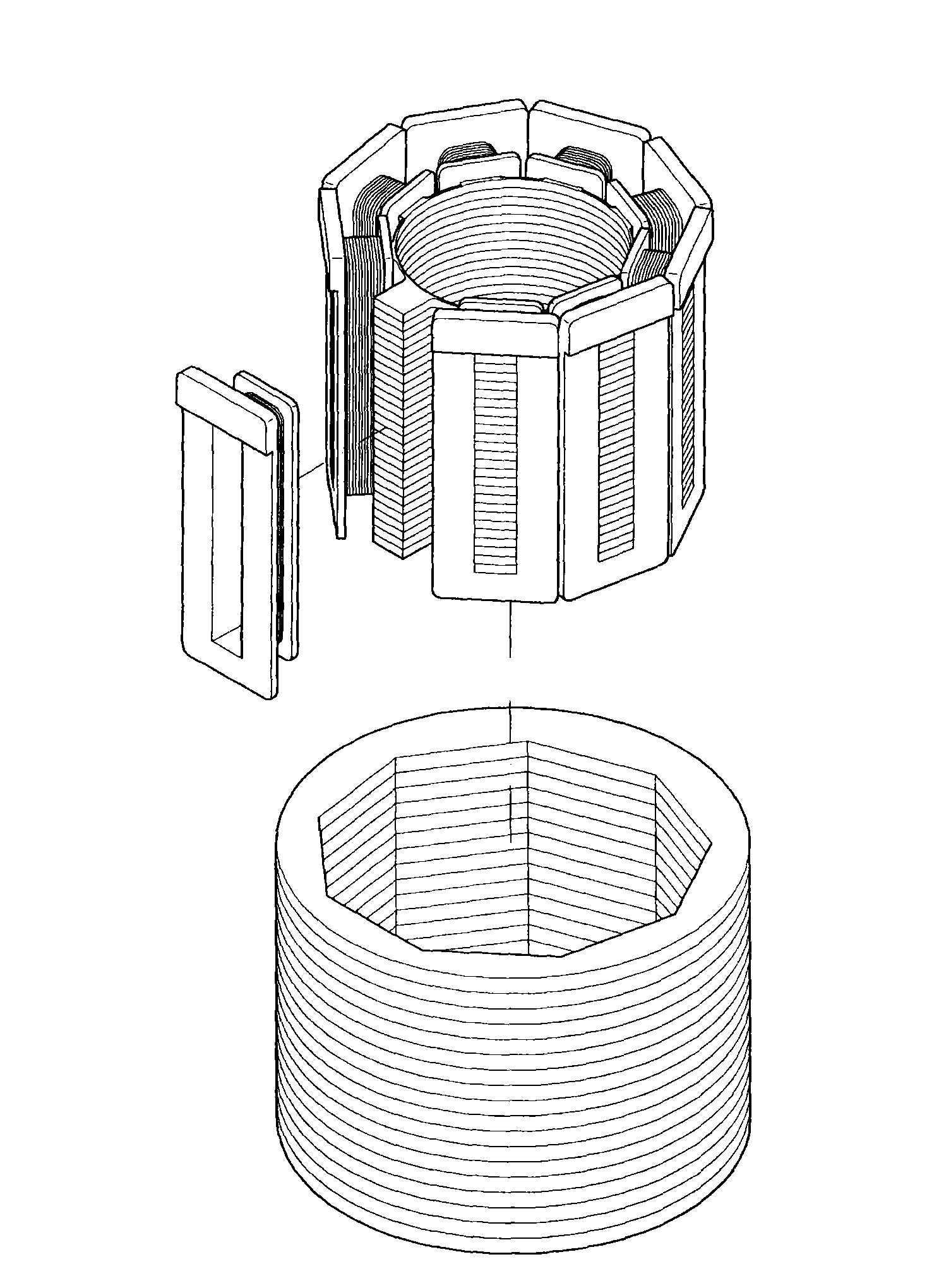
[0027] see Figure 4 As shown, it is a three-dimensional schematic diagram of the I-shaped monopole strips composed of the I-shaped monopole strips of the present invention. The manufacturing process of the motor stator of the present invention is firstly punching a plurality of silicon steel sheets with a precision I-shaped die to form a plurality of I-shaped monopole pieces 11, A plurality of I-type monopole sheets 11 are stacked one by one to form an I-type...


PUM


Abstract

The invention discloses a motor rotor structure and a manufacturing method thereof. The method comprises: punching silicon steel sheets to make a plurality of H-shaped single pole pieces; piling the H-shaped single pole pieces to make a plurality of H-shaped single pole bars; gluing the H-shaped single pole bars for adhesion; winding coils on each H-shaped single pole bar; surrounding and assembling the H-shaped single pole bars into a circle; and gluing the H-shaped single pole bars for adhesion to form a stator. The invention has the advantages of simple structure, low material cost, low mould development cost, better heat radiation effect, magnetic and iron loss reduction, efficiency increase and automatic mass production.

Description

technical field [0001] The invention relates to a motor stator structure and a manufacturing method thereof, in particular to a motor stator structure made of silicon steel sheets and a manufacturing method thereof, which can improve motor efficiency and reduce magnetic loss and iron loss. Background technique [0002] The motor has a wide range of uses and various types. It is mainly composed of a stator and a rotor. The stator can be an annular iron core (commonly known as an electromagnet) wound with a coil, covering the rotor. The rotor is a magnet. Rotate, but also vice versa, the stator is a magnet, and the rotor is an electromagnet. According to the application of the motor, it can generally be divided into speed control motor and precision control motor. The speed control motor is relatively simple and can control the rotation speed of the motor. The angle (or position) of rotation, such as a stepper motor or a servo motor. [0003] The torsion angle of the motor r...

Claims


Application Information

Patent Timeline
IPC IPC(8): H02K15/00H02K15/02H02K15/095H02K1/14H02K3/18
Inventor 王瑞亿
Owner HOFO AUTOMATION CO LTD
Learn More