Generator for converting air power into electric energy

An aerodynamic and electric energy conversion technology, which is applied in wind power generation, wind engines, wind engines consistent with the wind direction, etc., can solve problems such as poor controllability, inconvenient application, and inability to miniaturize, and achieve low noise, Easy setup and wide range of effects

Inactive Publication Date: 2010-01-20
辛见宽
View PDF0 Cites 1 Cited by
  • Summary
  • Abstract
  • Description
  • Claims
  • Application Information

AI Technical Summary

Problems solved by technology

[0002] The current wind power generation devices are all directly using the flow of air to convert the kinetic energy of the air flow into electrical energy; first of all, this type of power generation device is large-scale and cannot be miniaturized; secondly, they must be built in special places, generally located in natural places. High places, tuyere or windy belts, otherwise good results cannot be achieved. In short, they have many shortcomings, and it is inconvenient and not ideal to really be used in people's daily life; at the same time, when this type of power generation device is used, The air in nature is always flowing, but the speed of the air flow is not controlled by people, they can only be used, and the controllability is not good

Method used


Image

  • Generator for converting air power into electric energy
  • Generator for converting air power into electric energy
  • Generator for converting air power into electric energy

Examples


Embodiment Construction

[0009] Accompanying drawing is embodiment of the present invention.

[0010] The present invention will be further described below in conjunction with the accompanying drawings and embodiments.

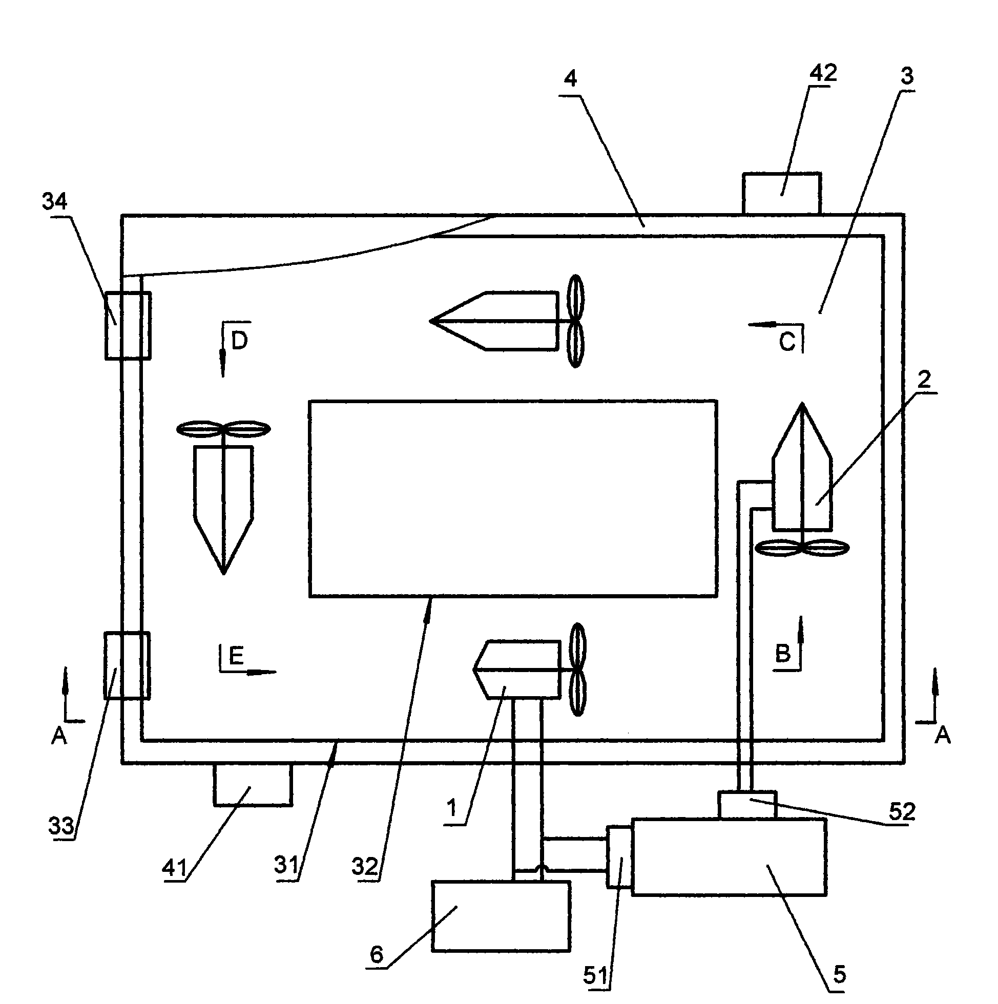
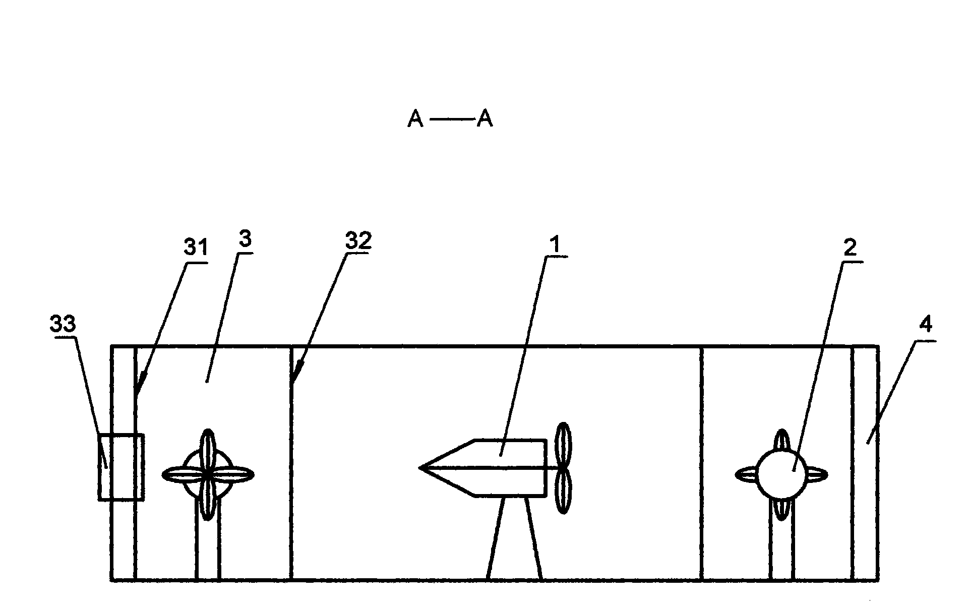
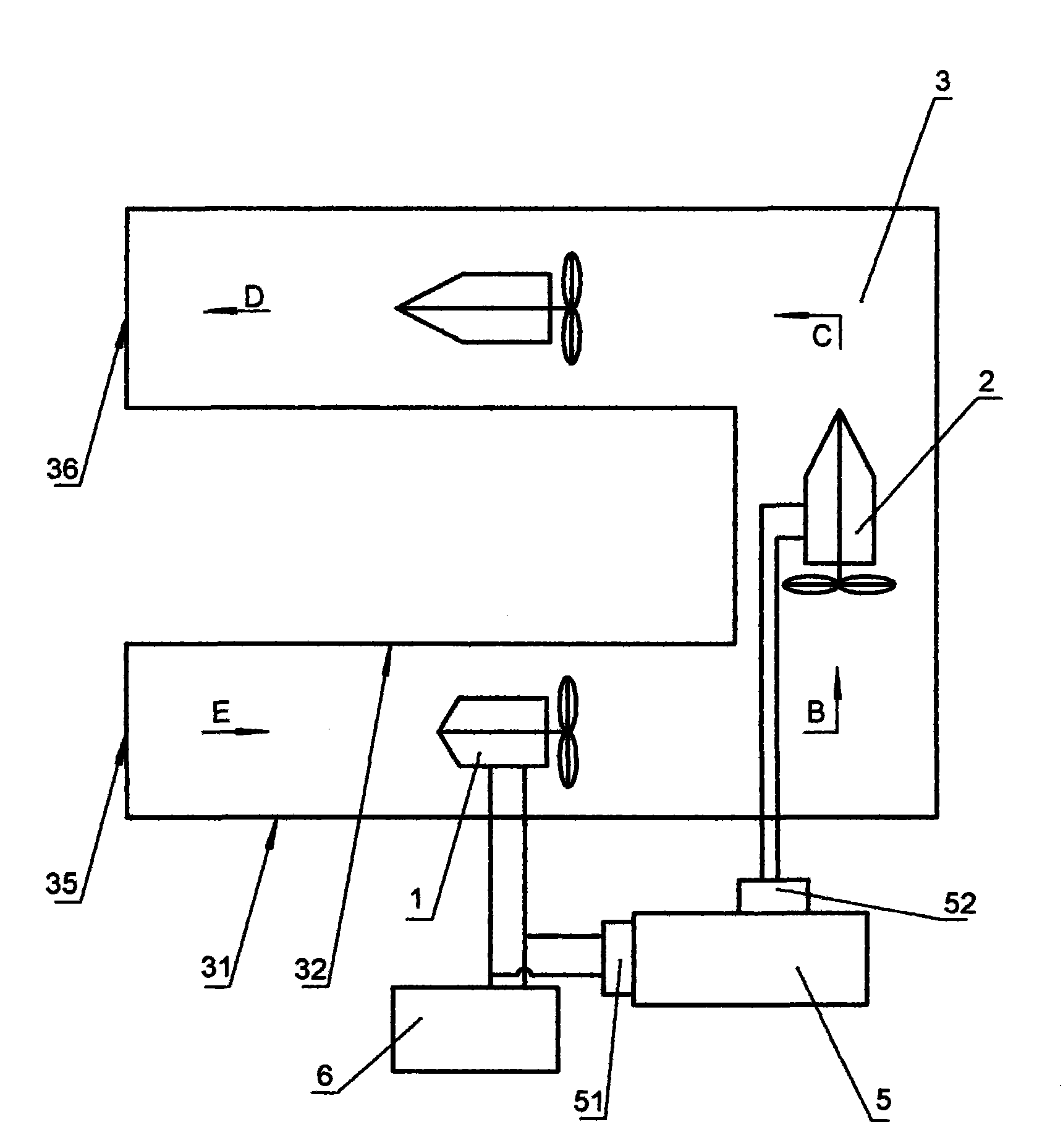
[0011] exist figure 1 Among them, the electrical energy conversion aerodynamic power generation device of the present invention is characterized in that it includes a fan 1, a wind generator 2, and an air duct 3. Facing the airflow B in the air duct 3; the air duct 3 is a fully enclosed circulating air duct; the air duct 3 has an outer wall 31 and an inner wall 32 of the air duct, and the outer wall 31 of the air duct and the inner wall of the air duct 32 is a space of "mouth" shape layout; the air duct outer wall 31 of the air duct 3 has a ventilation inlet 33 and a ventilation outlet 34 of a synchronous switch located on the side of the air duct 3 and communicated with it; There is a water cooling layer 4 outside the air duct 2, and the water cooling layer 4 has a water circulatio...


PUM


Abstract

The invention relates to a generator for converting air power into electric energy, comprising a fan, a wind driven generator and an air channel. The fan and the wind driven generator are sequentially located in the air channel, and the front surface of the wind driven generator faces to the coming direction of airflow in the air channel; the air channel is a full-close cyclic air channel or half-close air channel with two opened ends. When the air channel is the cyclic air channel, a square space is formed between the external wall and the internal wall of the air channel, the external wall of the air channel is provided with an air exchange inlet and an air exchange outlet of a synchronous switch arranged on one side of the air channel, wherein the air exchange inlet and the air exchange outlet are communicated with the air channel, the exterior of the air channel is provided with a water cooling layer with a water circulating inlet and a water circulating outlet. When the air channel has two opened ends, an n-shaped distribution space is formed between the external wall and the internal wall of the air channel; and the fan is connected with a power supplying end of an accumulator and an outside power source, and the wind driven generator is connected with the power storing end of the accumulator. The invention has convenient installation, wide application environment, controllable airflow, environment protection, low noise, safety and stability.

Description

technical field [0001] The invention relates to an energy conversion device, in particular to an air power generation device, which belongs to the field of energy. Background technique [0002] The current wind power generation devices are all directly using the flow of air to convert the kinetic energy of the air flow into electrical energy; first of all, this type of power generation device is large-scale and cannot be miniaturized; secondly, they must be built in special places, generally located in natural places. High places, tuyere or windy belts, otherwise good results cannot be achieved. In short, they have many shortcomings, and it is inconvenient and not ideal to really be used in people's daily life; at the same time, when this type of power generation device is used, The air is always flowing in nature, but people can't control the speed of the air flow, they can only use it, and the controllability is not good. Contents of the invention [0003] The object of...

Claims


Application Information

Patent Timeline
IPC IPC(8): F03D9/00F03D1/04F03D1/00F03D9/25
CPCY02E10/725Y02E10/72
Inventor 辛见宽
Owner 辛见宽
Why Eureka
Try Eureka