Cutting device of LCD panel

A liquid crystal panel and cutting device technology, which is applied to glass cutting devices, glass manufacturing equipment, manufacturing tools, etc., can solve the problems of reduced device operation rate and increased cost, and achieve the effect of reducing the installation area

Active Publication Date: 2013-07-24
SHIRAI IRON WORKS
View PDF1 Cites 0 Cited by
  • Summary
  • Abstract
  • Description
  • Claims
  • Application Information

AI Technical Summary

Problems solved by technology

[0010] Aiming at the deficiencies of the prior art, the object of the present invention is to provide a cutting device for liquid crystal panels, which solves the problem that the operation rate of the existing device is greatly reduced and the cost increases

Method used


Image

  • Cutting device of LCD panel
  • Cutting device of LCD panel
  • Cutting device of LCD panel

Examples


Embodiment Construction

[0051] Embodiments of the present invention will be described with reference to appended drawings.

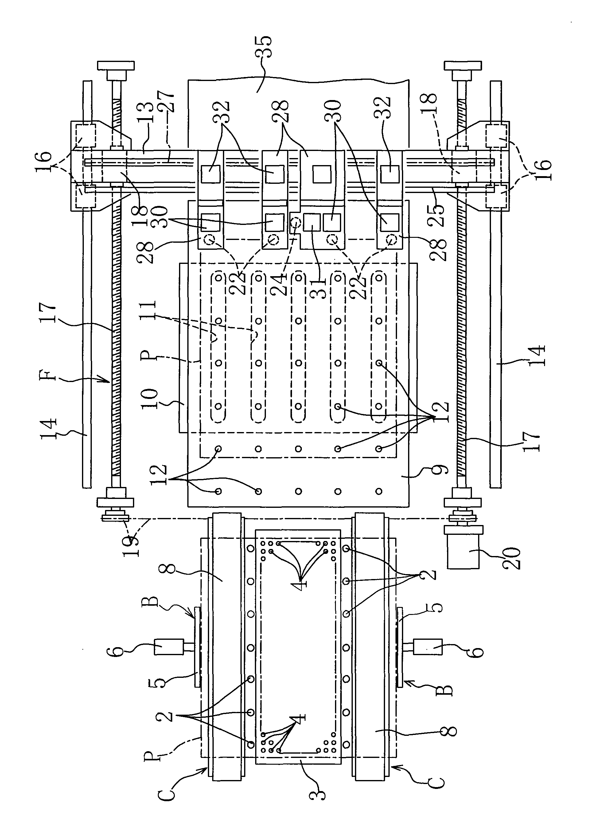
[0052] During the embodiment of the present invention, as Figure 1 to Figure 5 As shown, A is a supply platform for receiving large-scale liquid crystal panels P in a horizontal posture. The supply platform A is equipped with an adjustment means B for adjusting the received liquid crystal panels P, and the adjusted The liquid crystal panel P is supplied to the carrying-in means C ahead.

[0053] The charging of the above-mentioned liquid crystal panel P is as follows: Figure 6 Shown, to utilize the elongation of cylinder 1 to rise (as Figure 6 After the plurality of rows of pins 2 shown in the figure) are collected from the lower surface of the liquid crystal panel P dropped by the manipulator R, etc., the pins 2 are lowered by the contraction of the cylinder 1 and collected on the stage 3.

[0054] Thereafter, the liquid crystal panel P on the stage 3 is floated while th...


PUM


Abstract

The invention provides a cutting device of LCD panel marking the cutting lines on the A surface in the X and Y axe, marking the cutting lines for rough cutting and precious cutting on the B surface, and cutting each cutting line of a large LCD panel on a marking table of one production line. First and second cutters for marking in the X and Y axes are arranged on the marking table, in front of which a cutter of the cutting line for rough cutting, a cutting roller for cutting the cutting line, a cutter of the cutting line for precious cutting, and a cutting roller for cutting the cutting line are provided, and a first supplement table and a second supplement table for forward delivery are arranged above the cutters and cutting rollers, moreover, a cutting device is arranged in front of each supplement table.

Description

technical field [0001] The invention relates to a cutting device for roughly cutting a large liquid crystal panel (main glass substrate) into a product size, or roughly cutting a large liquid crystal panel and dividing it into a product size. Background technique [0002] In order to cut (or divide) large liquid crystal panels (for example, liquid crystal panels composed of two glass substrates bonded with thin film transistors and optical filters) into product sizes, A After cutting the cutting line (scribing line) on the surface (upper side) with the cutting knife on the first walking table, stop as the first walking table advances, and use the reversing device to lift the liquid crystal on the first walking table panel and rotate it 180 degrees (inverted). [0003] The liquid crystal panel after the 180-degree rotation is obtained by a transfer machine, and supplied to the second traveling table after obtaining. [0004] Secondly, make the second walking table carry out...

Claims


Application Information

Patent Timeline
Patent Type & Authority Patents(China)
IPC IPC(8): C03B33/023
Inventor 白井明
Owner SHIRAI IRON WORKS
Why Eureka
Try Eureka