
Imaging and projecting system for video conference

A projection system and video conferencing technology, applied in the physical field, can solve the problems of unsatisfactory image capture and projected images, and achieve the effect of enhancing the feeling and interaction, ensuring the quality of the camera, and reducing the area

Active Publication Date: 2011-01-26
SHANGHAI POSTS & TELECOMM DESIGNING CONSULTING INST
View PDF0 Cites 0 Cited by
  • Summary
  • Abstract
  • Description
  • Claims
  • Application Information

AI Technical Summary

Problems solved by technology

[0003] The object of the present invention is to provide a kind of imaging projection system for video conferencing, said a kind of imaging projection system for video conferencing should solve the problem of image capture and projection in the meeting room type video conferencing television system of the prior art Technical issues with unsatisfactory image effects

Method used


Image

  • Imaging and projecting system for video conference
  • Imaging and projecting system for video conference

Examples


Embodiment 1

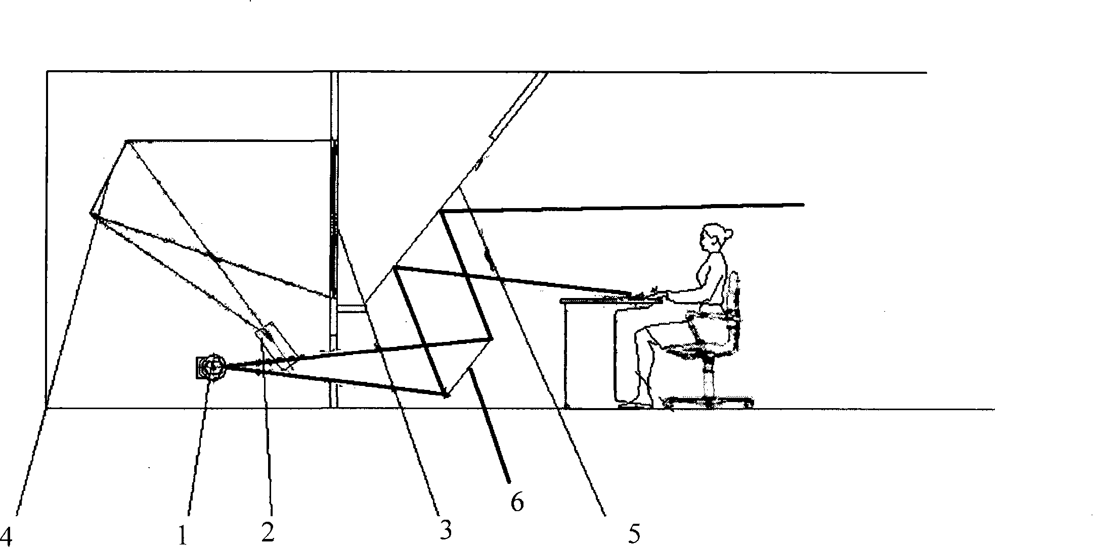
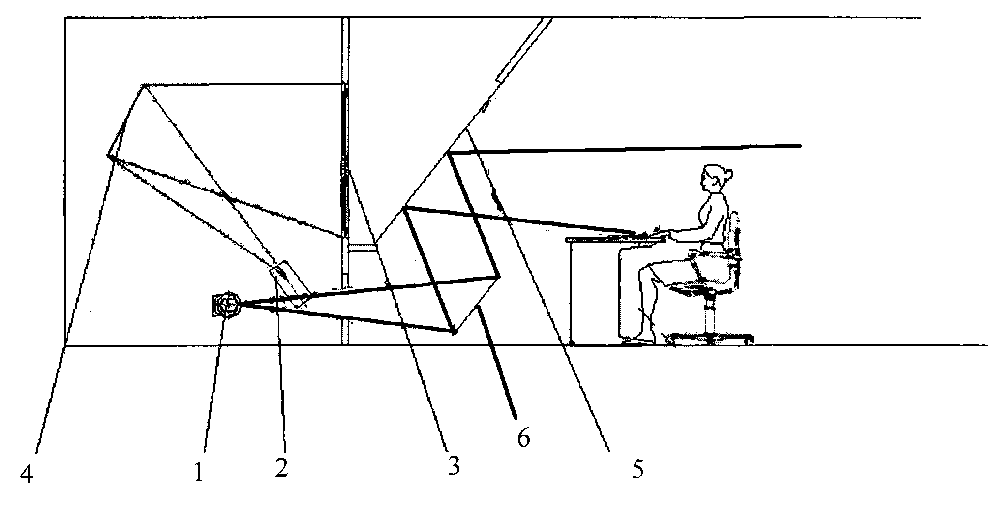
[0011] Such as figure 1 As shown, a kind of imaging projection system for video conferencing of the present invention is made of camera 1, projector 2, transmissive mirror 5, first mirror 6, second mirror 4 and rear projection screen 3, and its features In that: the transmissive mirror 5 is arranged in front of the rear projection screen 3, the first reflector 6 is arranged at the front and bottom of the rear projection screen 3, and the camera 1 is arranged at the bottom of the rear projection screen 3, The camera 1 is located in the reflection and outgoing light path of the transmissive mirror 5, the projector 2 is arranged behind the rear projection screen 3, the second reflector 4 is arranged behind the rear projection screen 3, and the second projector 4 is arranged behind the rear projection screen 3. The reflective surfaces of the two mirrors 4 are located in the outgoing light path of the projector 2 and the incident light path of the rear projection screen 3 .

[001...


PUM


Abstract

The invention relates to an imaging and projecting system for a video conference, which consists of a camera, a projector, a transmission reflector and a rear projection screen. The camera is arranged behind the rear projection screen, the reflector is arranged behind the rear projection screen, the reflecting surface of the first reflector is positioned in the emergent optical path of the cameraand the incident optical path of the rear projection screen, the transmission reflector is arranged in front of the rear projection screen, the camera is arranged below the transmission reflector andthe camera is positioned in the reflective emergent optical path of the transmission reflector. The imaging and projecting system utilizes the rear projection screen to reproduce images of persons inthe video signals from the remote conference, reduces the distance between the projector and the rear projection screen by the reflector, reflects the front images of the conference attendees to the camera by the transmission reflector and then transfers the front images to the remote conference. The invention realizes short-distance image pick-up of the camera, guarantees the pick-up quality, reduces the requirements of equipment on the area of the conference room, and enhances the feeling of conference attendees for face-to-face communication and interaction.

Description

Technical field: [0001] The invention relates to the field of physics, in particular to optics, in particular to an imaging projection system for video conferencing. Background technique: [0002] In the traditional meeting room type video conferencing TV system, in order to avoid the distortion of the image of the person caused by the up and down deviation of the person's line of sight when capturing the image, the camera needs to be set in the center facing the participants and kept at the level of the person's line of sight, so it is necessary to have a large enough Only a large conference room can achieve strong interactivity, and the distance between the rear projection screen and the participants is relatively long, and the conference effect is poor. Invention content: [0003] The object of the present invention is to provide a kind of imaging projection system for video conferencing, said a kind of imaging projection system for video conferencing should solve the p...

Claims


Application Information

Patent Timeline
Patent Type & Authority Patents(China)
IPC IPC(8): G03B17/54G03B17/17
Inventor 张芸郑翚马云伟宋玲玲
Owner SHANGHAI POSTS & TELECOMM DESIGNING CONSULTING INST
Learn More