
LED light source with semiconductor heat dissipation device

A technology of LED light source and heat dissipation device, applied in the field of LED light source, can solve the problems of slow heat dissipation, unsatisfactory effect, large temperature influence, etc., and achieve the effects of convenient temperature, reduction of light decay, and prolongation of service life

Inactive Publication Date: 2010-01-06
SHENZHEN HOYOL OPTO ELECTRONICS
View PDF0 Cites 9 Cited by
  • Summary
  • Abstract
  • Description
  • Claims
  • Application Information

AI Technical Summary

Problems solved by technology

This heat dissipation method belongs to passive heat dissipation, and its disadvantage is that the heat dissipation speed is slow, and it is greatly affected by the ambient temperature, so the effect is not ideal

Method used


Image

  • LED light source with semiconductor heat dissipation device
  • LED light source with semiconductor heat dissipation device

Examples


Embodiment Construction

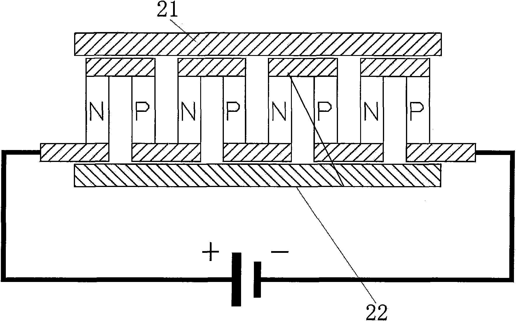
[0014] Semiconductor refrigeration principle such as figure 1 shown. When the semiconductor material is energized, a cold end 21 and a hot end 22 are generated on both sides of the semiconductor. The cold end will continuously absorb heat from the surrounding environment, and transfer the absorbed heat to the hot end through the thermal movement of molecules. The temperature difference between the cold and hot ends Up to tens of degrees.

[0015] This invention utilizes this feature of semiconductor refrigeration to closely connect the cold end and the heat concentration point on the back of the LED high-power light source, so that the semiconductor refrigeration sheet absorbs the heat generated by the LED, and conducts the absorbed heat to its hot end, and then , and then dissipate into the environment.

[0016] In a preferred embodiment of the present invention, a heat sink can also be connected to the hot end of the semiconductor refrigerating sheet, and the heat of the s...


PUM


Abstract

The invention discloses an LED light source with a semiconductor heat dissipation device, comprising the LED light source and a semiconductor refrigeration sheet, wherein the cold end of the semiconductor refrigeration sheet is closely connected with the back surface of the LED light source, and the hot end of the semiconductor refrigeration sheet is closely connected with a heat dissipater; when the LED light source works, the cold end of the semiconductor refrigeration sheet absorbs heat generated by the LED light source and conducts the heat to the hot end, and then the hot end discharges the heat to surrounding environment through the heat dissipater connected with the hot end, thus, an LED is kept to work under environment with lower temperature.

Description

technical field [0001] The invention relates to LED light source technology, in particular to an LED light source with a semiconductor cooling device. Background technique [0002] In the manufacture of high-power LEDs, dozens of tube cores need to be concentrated in a small range, and each tube core will generate heat during use, which will cause the local temperature of the LED to be high, such as LED light source The heat of the light source cannot be dissipated quickly, which will increase the light decay of the light source and affect its service life. The heat dissipation method in the prior art is to directly connect the LED high-power light source to the radiator, and let the heat dissipate naturally through the temperature difference. This heat dissipation method belongs to passive heat dissipation, and its disadvantage is that the heat dissipation speed is slow, and it is greatly affected by the ambient temperature, so the effect is not ideal. [0003] Therefore,...

Claims


Application Information

Patent Timeline
Patent Type & Authority Applications(China)
IPC IPC(8): F21V29/00H01L23/34F21Y101/02F21V29/508F21V29/71
Inventor 杨向红常保延郭印文
Owner SHENZHEN HOYOL OPTO ELECTRONICS
Learn More