Impact wrench

An impact wrench, non-impact technology, applied in the field of impact wrench, can solve problems such as tilt danger

Inactive Publication Date: 2010-01-06
麦太保有限公司
View PDF9 Cites 9 Cited by
  • Summary
  • Abstract
  • Description
  • Claims
  • Application Information

AI Technical Summary

Problems solved by technology

[0009] The disadvantage of this configuration is that the inclination of the impact dog of the anvil or hammer body relative to the hammer seat and the drive shaft is dangerous

Method used


Image

  • Impact wrench
  • Impact wrench
  • Impact wrench

Examples


Embodiment Construction

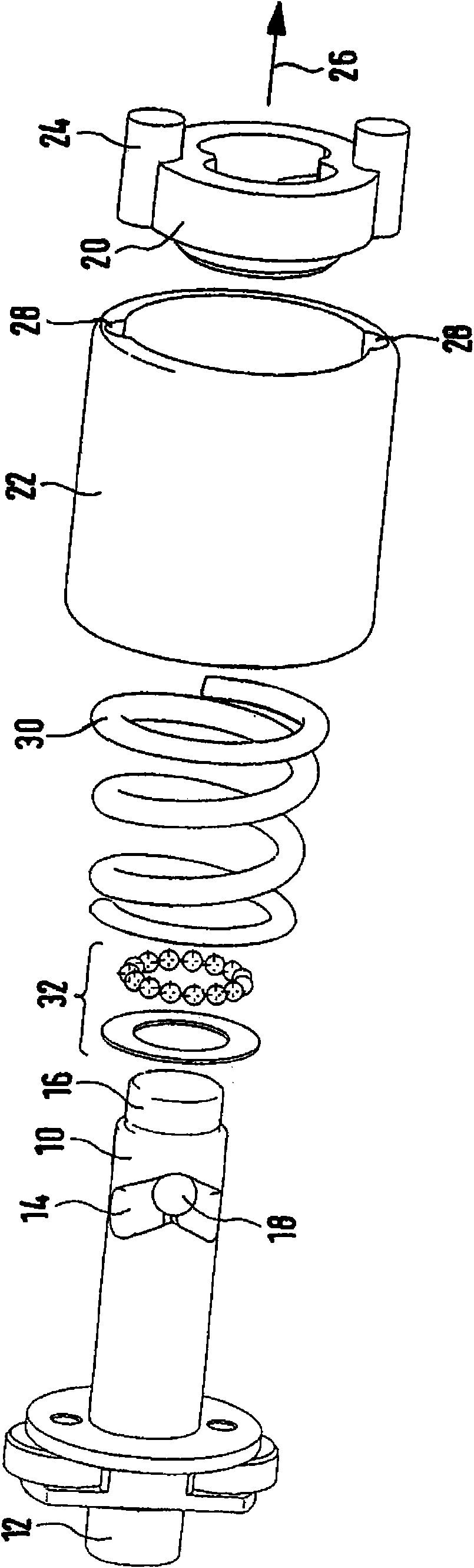
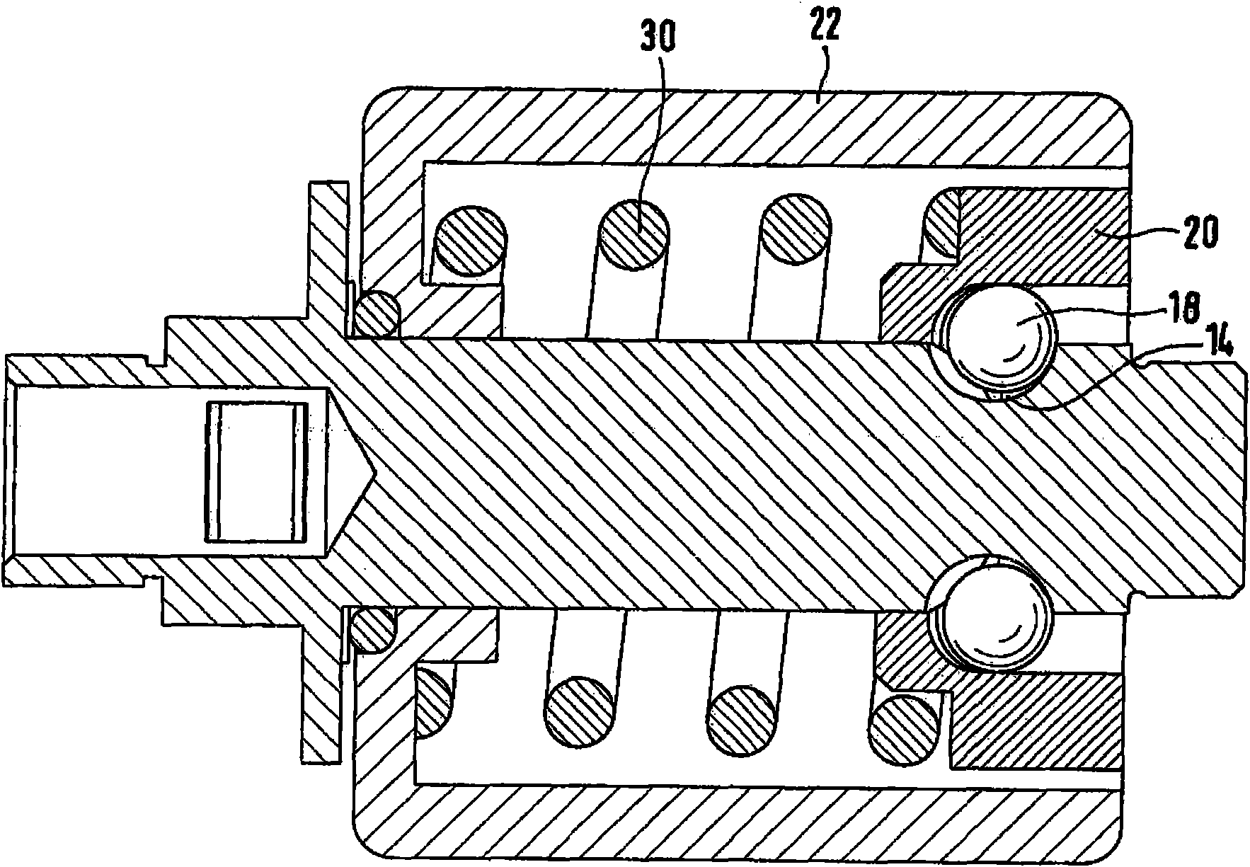
[0031] figure 1 Shown is an impact device according to the invention having a drive shaft 10 comprising a drive-side end 12 by means of which the drive shaft 10 can communicate with a drive motor (not shown), in particular via a transmission. ) coupling. A V-shaped groove 14 is provided on the transmission shaft 10 , wherein the apex of the V-shaped groove points toward the output-side end 16 of the transmission shaft 10 . Balls 18 are respectively introduced into V-shaped grooves 14, wherein two grooves 14 are arranged diametrically opposite each other on the transmission shaft 10, wherein corresponding running surfaces (not shown) for receiving balls 18 are provided in control element 20 out). Via the groove 14 and the ball guide 18 , the control part 20 is movable relative to the drive shaft 10 in the region of the groove 14 and in particular can perform axial and rotational oscillating movements. The percussion device also includes a rotating mass 22 , wherein the revol...


PUM


Abstract

The invention relates to an impact wrench having a drive motor for driving a drive shaft (10) and an output shaft (38) that can be coupled to a tool holder, and having an impact mechanism, the impact mechanism comprising an anvil (36) that has first impact cheeks (34) and that is coupled to the output shaft (38), and comprising a hammer, which is guided on the drive shaft (10), the hammer having second impact cheeks (24), which engage with the first impact cheeks (34) for the purpose of rotary transmission, wherein the hammer comprises a rotating mass (22) and a control part (20), the controlpart (20) carrying the second impact cheeks (24) and rotating with the drive shaft (10) in the case of non-impact and, in the case of impact, executing an axial and, preferably, additional, rotational oscillation relative to the drive shaft (10), the control part (20) transmitting the rotation of the drive shaft (10) to the rotating mass (22) and being movably guided in the axial direction in therotating mass (22) for the purpose of realizing the impact function, and the rotating mass (22) not executing any axial movement.

Description

technical field [0001] The invention relates to an impact wrench for screwdriving and drilling, which has a rotary impact device, wherein such an impact wrench is also used in order to form or release high-strength screw connections. Background technique [0002] Impact wrenches have been known in the prior art for many years, in which the function of the rotary impact device is based on the idea that the drive energy of the motor is temporarily stored and periodically released to the output shaft within very short working periods. Depending on the duration of the pulses, these periodically released rotational pulses generate a resultant transmission torque which is significantly higher than would be possible with a constant torque distribution. The system receives kinetic energy from the drive in the form of torque and rotational speed, wherein this kinetic energy is temporarily stored in components, for example in springs or rotating masses. The storage process lasts unti...

Claims


Application Information

Patent Timeline
IPC IPC(8): B25B21/02
CPCB25B21/02B25B21/026
Inventor 本亚明·安德尔
Owner 麦太保有限公司
Why Eureka
Try Eureka