
Air outlet and method for the production thereof

一种排气口、空气出口的技术,应用在排气口及其制造领域,能够解决限制通风效果、排气口孔板的内衬不可能实现等问题,达到快速安装的效果

Active Publication Date: 2013-04-24
CAVERION
View PDF5 Cites 0 Cited by
  • Summary
  • Abstract
  • Description
  • Claims
  • Application Information

AI Technical Summary

Problems solved by technology

Lining of the vent orifice is generally not possible as it severely limits the desired ventilation effect

Method used


Image

  • Air outlet and method for the production thereof
  • Air outlet and method for the production thereof
  • Air outlet and method for the production thereof

Examples


Embodiment Construction

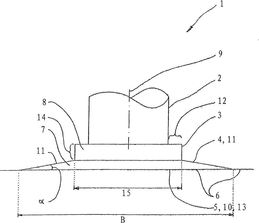
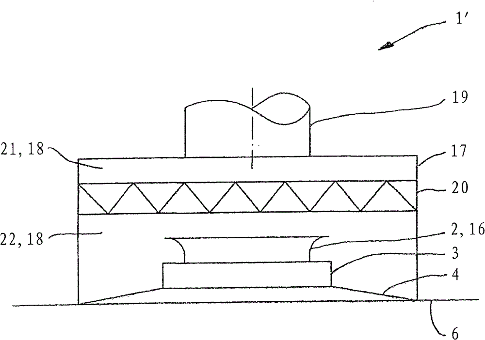
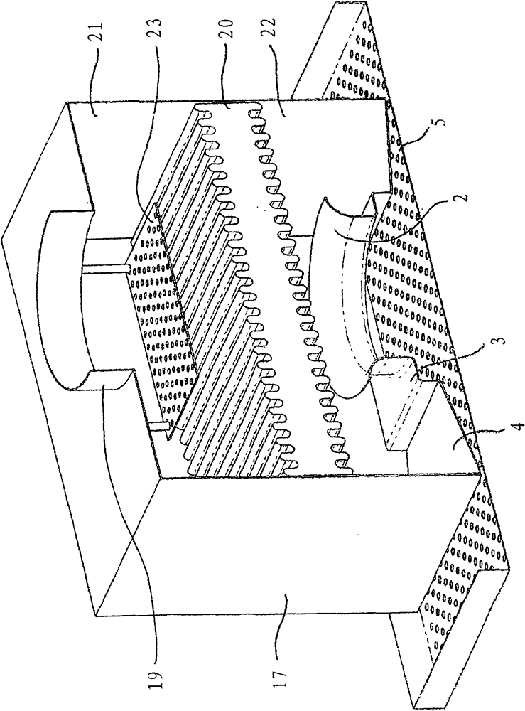
[0028] exist figure 1 Essential components of the invention can be seen in the shown vertical section through a first embodiment of an air outlet 1 according to the invention, in particular a ceiling air outlet. The exhaust port 1 has a connection 2 for at least indirect connection to an air supply system (not shown). Firstly a transition piece is connected to the connection piece 2 and then the housing 4 is attached, which in turn is attached to a ceiling panel 6 designed as a perforated plate 5 . The air distribution chamber 7 is delimited by the ceiling panel 6 and the housing 4 , and the interior cavity 8 of the transition section 3 can likewise be regarded as an air distribution chamber. The center line 9 of the socket 2 runs perpendicularly to the ceiling panel 6 .

[0029] Initially, that is to say before the start of assembly, only the connecting piece 2, the transition piece 3 and the housing 4 form a unit which is not yet functional and has a completely free air ou...


PUM


Abstract

The invention relates to an air outlet (1, 1'), comprising a connecting piece (2) for the at least indirect connection to an air supply system, a housing (4) delimiting an air distribution chamber (7), and a perforated plate (5) forming an effective air discharge cross-section (10) of the air outlet (1, 1'), wherein a center line (9) of the connecting piece (2) is oriented perpendicular to the perforated plate (5). Starting from a center region of the housing (4), in which the connecting piece (2) empties into the air distribution chamber (7), walls (11) of the housing (4) that face the perforated plate (5) wrap around and extend in the direction of the perforated plate (5), inclined at an acute angle alpha in relation to the perforated plate (5). The invention further relates to a suspended ceiling or a wall paneling, and to a method for producing a previously described air outlet (1, 1'). In order to refine the air outlet known from the state of the art regarding the flow behavior of the escaping air, and in order to improve the optical properties and provide a simplified method for producing an air outlet, according to the invention the perforated plate (5) is a panel (6) of a louvered ceiling or a wall paneling.

Description

technical field [0001] The invention relates to an air outlet comprising a connection at least indirectly to an air supply system, a housing defining an air distribution chamber, and an orifice forming an effective air outlet section of the air outlet, wherein the center line of the connection is vertical Oriented to the perforated plate, starting from the central area of ​​the housing where the connection pipes open into the air distribution chamber, the wall of the housing facing the perforated plate extends annularly and obliquely at an acute angle α to the perforated plate in the direction of the perforated plate. Furthermore, the invention relates to a suspended ceiling or wall lining and a method for producing the above-mentioned air outlet. Background technique [0002] Outlet outlets known from the prior art typically use deflectors such as vanes or deflector vanes in order to achieve a turbulent mixed ventilation. However, such an air vent has the disadvantage that...

Claims


Application Information

Patent Timeline
Patent Type & Authority Patents(China)
IPC IPC(8): F24F13/068F24F7/10
CPCF24F7/10F24F13/062F24F13/068Y10T29/49826
Inventor 埃克哈德·菲德勒
Owner CAVERION
Learn More