
Aerated building block transfer system

A technology of aerated blocks and transfer racks, applied in railway braking systems, buildings, building structures, etc., can solve problems affecting the stability of aerated blocks, high cost, and low transportation efficiency, and achieve improved stability and transshipment efficiency, the effect of reducing labor costs

Pending Publication Date: 2020-12-22
苏州良浦天路新型建材有限公司
View PDF0 Cites 0 Cited by
  • Summary
  • Abstract
  • Description
  • Claims
  • Application Information

AI Technical Summary

Problems solved by technology

[0003] Aerated concrete blocks need to be transferred to other stations after prefabrication and production. The existing transfer method is to transport by transport vehicles, which is costly and inefficient. The high cost is specifically labor costs, and the transportation of human-driven transport vehicles will Affected by the subjective factors of the transporter, such as fatigue and other mistakes will affect the stability of the aerated block during transportation, and the structure of the transfer frame used for transportation is simple, it is difficult to avoid the aerated block during transportation. Collision occurs

Method used


Image

  • Aerated building block transfer system
  • Aerated building block transfer system
  • Aerated building block transfer system

Examples


Embodiment 1

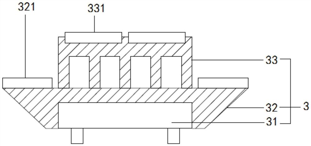
[0025] see Figure 1 to Figure 4 , the present embodiment provides an aerated block transfer system, first of all, a traction device, a brake device and a quick-load transfer frame 3 are provided, the traction device includes a first guide rail 11 and a driving assembly, and the first guide rail 11 is laid on the ground, The opposite ends of the first guide rail 11 are respectively the starting point of transfer and the end point of transfer. The fast loading transfer frame 3 is slidably installed on the first guide rail 11. The fast loading transfer frame 3 moves towards the starting point or end point of transfer under the drive of the drive assembly, and brakes The device includes a second guide rail 21, a brake pad mounting base 22 and a brake pad body 23. The second guide rail 21 is located in the middle of the first guide rail 11. The brake pad mounting base 22 is fixedly connected to the quick-load transfer frame 3 and slides on the second guide rail 21. , The brake pad...

Embodiment 2

[0033] see Figure 1 to Figure 4 , the figure shows an aerated block transfer system provided by Embodiment 2 of the present invention. On the basis of the above-mentioned embodiments, this embodiment further makes the following technical solutions as improvements: in Embodiment 1 The fast-loading transfer frame is a boat-shaped transfer frame. In order to maintain stability during transportation, the same amount of aerated blocks needs to be placed on both ends of the ship-shaped transfer frame, so that the boat-shaped transfer frame can maintain balance on both sides.

Embodiment 3

[0035] see Figure 1 to Figure 4 , the figure shows an aerated block transfer system provided by Embodiment 3 of the present invention. This embodiment further makes the following technical solutions as improvements on the basis of the above-mentioned embodiments: In order to further improve the fast For the stability of the transfer rack during transportation, an anti-tipping bar is welded on opposite ends of the quick-load transfer rack. The bottom end of the tipping bar will touch the ground, so as to prevent the quick-load transfer frame from tipping over at a greater angle.


PUM


Abstract

The invention provides an aerated building block transfer system. Firstly, a traction device, a brake device and a fast assembling transfer frame are arranged; the traction device comprises a first guide rail and a driving assembly; the first guide rail is laid on the ground; the two opposite ends of the first guide rail are respectively a transfer starting point and a transfer ending point; the fast assembling transfer frame is glidingly arranged on the first guide rail, and is driven by a driving assembly to move towards the transfer starting point or the transfer ending point; the brake device comprises a second guide rail, a brake block installing seat and a brake block body; the second guide rail is positioned in the middle part of the first guide rail; the brake block installing seatis fixedly connected with the fast assembling transfer frame, and slides on the second guide rail; the brake block body is arranged on the brake block installing seat; and the bottom end of the brakeblock body is tightly abutted against the ground. Compared with the prior art, the aerated building block transfer system has the advantages that a transfer system is provided for a transfer trolleyof aerated building blocks; convenience is provided for the transfer of the aerated building blocks; the stability and the transfer efficiency of the aerated building blocks in the transfer process are improved; and the labor cost is reduced.

Description

technical field [0001] The invention relates to the transfer of aerated concrete blocks, in particular to an aerated block transfer system. Background technique [0002] Air-entrained concrete block is a new type of building material that is lightweight, porous, thermal insulation, good fire resistance, nailable, sawable, planable, and has certain earthquake resistance. As early as the early 1930s, China began to produce this product, and it was widely used in high-rise frame structure buildings. It is an excellent new building material and has the advantages of environmental protection. [0003] Air-entrained concrete blocks need to be transferred to other stations after prefabrication and production. The existing transfer method is to transport by transport vehicles, which is costly and inefficient. The high cost is specifically labor costs, and the transportation of human-driven transport vehicles will Affected by the subjective factors of the transporter, such as fatig...

Claims


Application Information

Patent Timeline
Patent Type & Authority Applications(China)
IPC IPC(8): E04G21/16B61H11/00
CPCB61H11/00E04G21/162
Inventor 蒋士奇朱欢劼赵斌卢耀武陆彬张建刚王聿暐陈中梁本玉
Owner 苏州良浦天路新型建材有限公司
Learn More