
Liquid crystal display device

A liquid crystal display and device technology, applied to LCD. field, can solve problems such as image defects, liquid crystal leakage of the liquid crystal layer 6, etc.

Active Publication Date: 2009-12-30
LG DISPLAY CO LTD
View PDF0 Cites 8 Cited by
  • Summary
  • Abstract
  • Description
  • Claims
  • Application Information

AI Technical Summary

Problems solved by technology

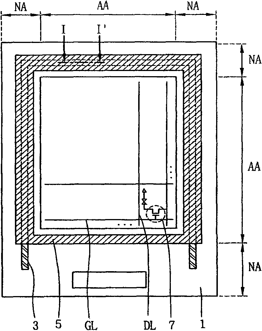
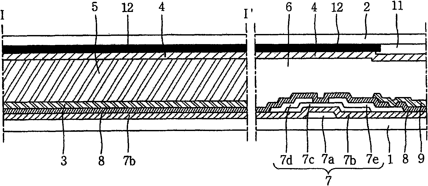
Therefore, if an external force (such as a force that pulls the first or second substrate) is applied to the first or second substrate 1 or 2, the portion bonded to the common line 3 or the common electrode 4 will often be in the sealant. A certain area of ​​5 is disengaged, which causes the liquid crystal in the liquid crystal layer 6 to leak out, resulting in image defects

Method used


Image

  • Liquid crystal display device
  • Liquid crystal display device
  • Liquid crystal display device

Examples


Embodiment Construction

[0023] A liquid crystal display device (LCD) according to an exemplary embodiment of the present invention will now be described with reference to the accompanying drawings.

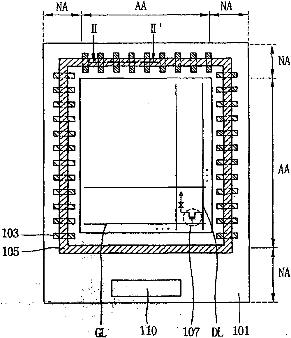
[0024] Figure 3a is a plan view of a first substrate 101 of an LCD according to an embodiment of the present invention, Figure 3b is a plan view of the second substrate 102 of the LCD. For the sake of explanation, Figure 3a and 3b Encapsulant 105 is shown. Figure 4 The left area shows along the Figure 3a The line II-II' in and Figure 3b The section cut by the line III-III’ in Figure 4 The right region of , shows a cross-section of a region in which a thin film transistor (TFT) 107 is formed in a pixel defined on the first and second substrates 101 and 102 .

[0025] like Figure 3a to Figure 4 As shown, an LCD according to one embodiment of the present invention includes first and second substrates 101 and 101 on which a display area (AA) and a non-display area (NA) are defined and a plura...


PUM


Abstract

A liquid crystal display includes: first and second substrates on which a display area and a non-display area are defined and a plurality of pixels are defined at the display area; a pixel electrode formed at each pixel on the first substrate; a plurality of first attachment improving protrusions formed at the non-display area along edges of the display area on the first substrate and made of the same material as the pixel electrode on the layer on which the pixel electrode is formed; a common electrode formed at least on a display area of the second substrate; a plurality of second attachment improving protrusions formed on the non-display area of the second substrate and branched off from the common electrode; and a sealant formed between the first and second substrates such that the sealant is attached with the first and second attachment improving protrusions, and having conductivity, wherein the common electrode receives a, common voltage via the sealant and the first attachment improving protrusions.

Description

technical field [0001] The present invention relates to a liquid crystal display device (LCD), and more particularly to a method capable of increasing the adhesion of a sealant formed between a first substrate, a thin film transistor (TFT) substrate, and a second substrate, a color filter substrate ( Attachment) area to improve the adhesive (adhesive) strength of the LCD sealant. Background technique [0002] In general, a liquid crystal display device (LCD) has expanded its application range due to its lightness, thinness, and low power consumption driving characteristics. Thus, LCDs are commonly used as devices for displaying images in portable computers, mobile phones, office automation instruments, and the like. [0003] The LCD controls the amount of transmitted light according to video signals applied to a plurality of control switching elements arranged in a matrix, thereby displaying desired images on the screen. [0004] The LCD includes a liquid crystal panel inc...

Claims


Application Information

Patent Timeline
IPC IPC(8): G02F1/1339G02F1/13
CPCG02F2201/121G02F1/1333G02F2001/133388G02F1/1339G02F1/133388G02F1/1343
Inventor 姜在洙金旲奎
Owner LG DISPLAY CO LTD
Learn More