
Quality detection device for concave-convex printed product

A technology for detection devices and printed matter, applied in measuring devices, material analysis through optical means, instruments, etc., to achieve the effect of solving uneven defects

Active Publication Date: 2009-12-30
SHANGHAI SPINNING DYEING PRINTING PACKAGING +3
View PDF0 Cites 7 Cited by
  • Summary
  • Abstract
  • Description
  • Claims
  • Application Information

AI Technical Summary

Problems solved by technology

[0005] The object of the present invention is to provide a quality inspection device for concave-convex printed matter, which effectively solves the problem of concave-convex imaging and makes it possible to detect concave-convex defects

Method used


Image

  • Quality detection device for concave-convex printed product

Examples


Embodiment Construction

[0011] The present invention will be further described in detail below in conjunction with the accompanying drawings and embodiments.

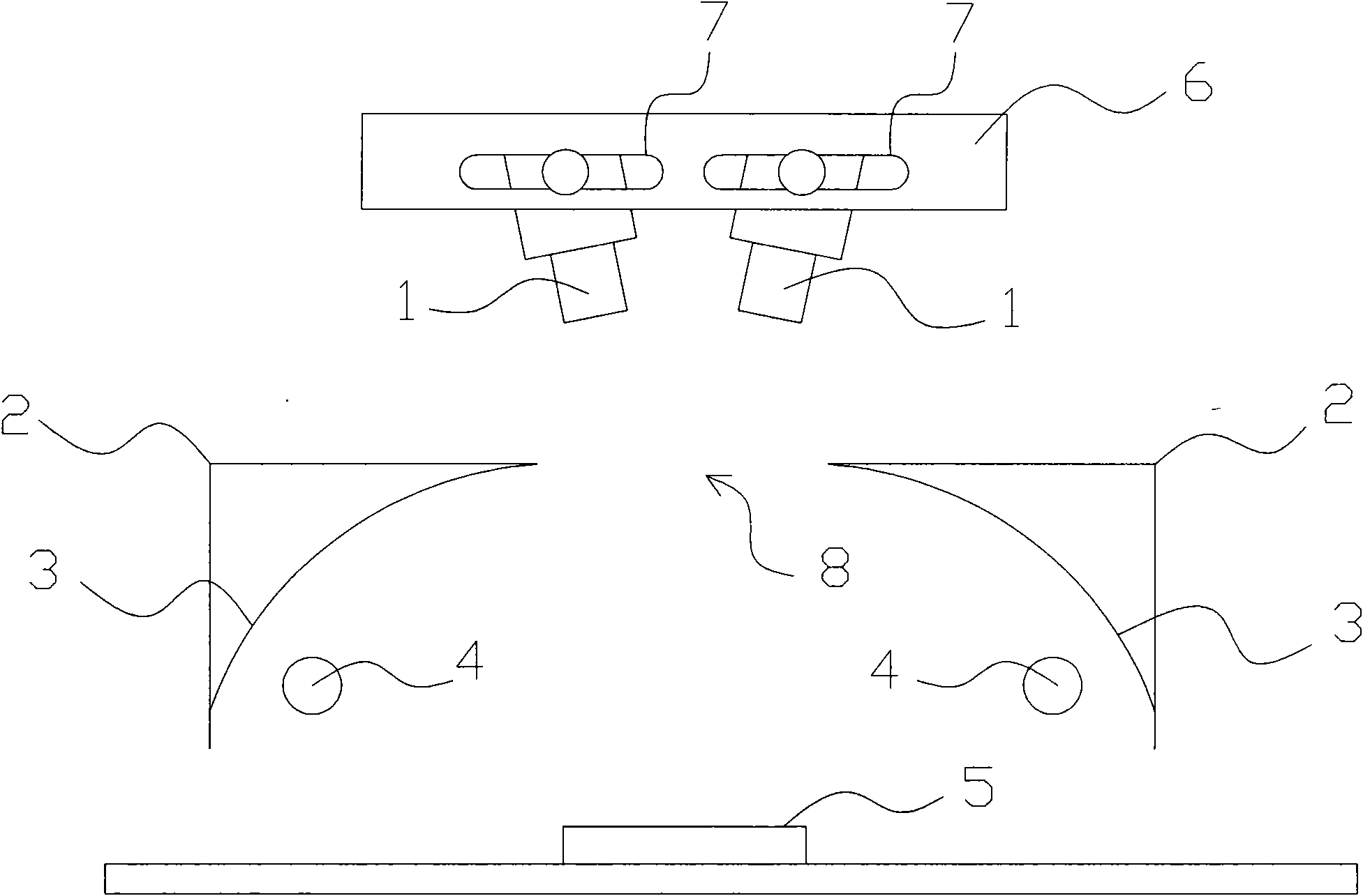
[0012] see figure 1 , the invention discloses a quality inspection device for concave-convex printed matter, which includes a camera group, a closed light box 2 and a camera clamping mechanism 6, and the camera group is installed above the printed matter 5 to be detected through the camera clamping mechanism 6, said The camera 1 in the camera group can adjust the shooting angle arbitrarily through the adjusting device 7 on the camera clamping mechanism 6. The adjusting device includes slots on both sides of the camera clamping mechanism and screws passing through the slots. The camera is adjusted and adjusted by the screws. Fixed, the closed light box 6 is located between the camera group and the printed matter 5, a slit 8 is arranged in the middle of the light box 2, and the camera 1 captures the image of the printed matter through the slit 8...


PUM


Abstract

The invention discloses a quality detection device for a concave-convex printed product, which comprises a camera set, a closed type lamp box and a camera clamping mechanism, wherein the camera set is arranged on the upper part of a printed product to be detected through the camera clamping mechanism; the closed type lamp box is positioned between the camera set and the printed product to be detected, and a narrow gap is reserved in the middle of the lamp box; and the camera set shoots and acquires images of the printed product through the narrow gap. The quality detection device is characterized in that the camera set comprises two cameras which are symmetrically distributed; and the cameras can randomly adjust shooting angles through an adjustment device on the camera clamping mechanism. By adopting the technical scheme, the shot images have good concave-convex effect; shooting are performed by the two cameras in a symmetrical mode to obtain the images with complementary concave-convex effect to further solve the problem of roughness.

Description

technical field [0001] The invention relates to a quality detection device for printed matter, in particular to a quality detection device for concave-convex printed matter. Background technique [0002] The existing quality inspection device for printed matter mainly includes a camera, a light box and a camera clamping mechanism. The camera is fixedly installed above the tested printed matter through the camera clamping mechanism. The light box is located between the camera group and the tested printed matter. A slit is provided; the camera shoots and collects the image of the printed matter through the slit. [0003] With the development of the printing industry, people have higher requirements for packaging and decoration. They require bright colors. Increase the level of three-dimensional sense. [0004] However, because most of the existing detection devices use diffuse light sources and only use vertical angles for image acquisition, the shooting effect has not been ...

Claims


Application Information

Patent Timeline
Patent Type & Authority Applications(China)
IPC IPC(8): G01N21/956
Inventor 蔡春华杨孝刚吴伟泉
Owner SHANGHAI SPINNING DYEING PRINTING PACKAGING
Learn More