Clamp for rail fatigue experiment acted by bending moment

A technology of fatigue experiment and fixture, which is applied in the direction of applying stable bending force to test the strength of materials, measuring devices, instruments, etc. It can solve the problems of providing, not being able to simulate the working conditions of rail materials, difficult rails, etc., and achieve simple test operation, Easy replacement of the loading head, high correlation effect

Inactive Publication Date: 2011-08-24
SOUTHWEST JIAOTONG UNIV
View PDF2 Cites 0 Cited by
  • Summary
  • Abstract
  • Description
  • Claims
  • Application Information

AI Technical Summary

Problems solved by technology

During the experiment, the two ends of the sample are not fixed and have multiple degrees of freedom, so it is impossible to simulate the working conditions of the rail material in the actual use process with bending moment, so the experimental results are difficult to provide reliable information for the material selection, design and manufacture of the rail. , valid basis

Method used


Image

  • Clamp for rail fatigue experiment acted by bending moment
  • Clamp for rail fatigue experiment acted by bending moment
  • Clamp for rail fatigue experiment acted by bending moment

Examples


specific Embodiment approach

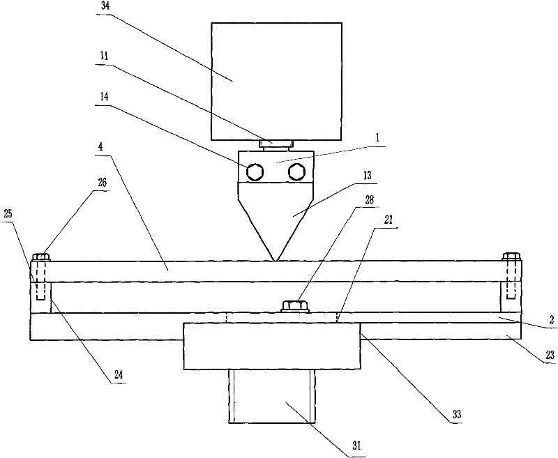
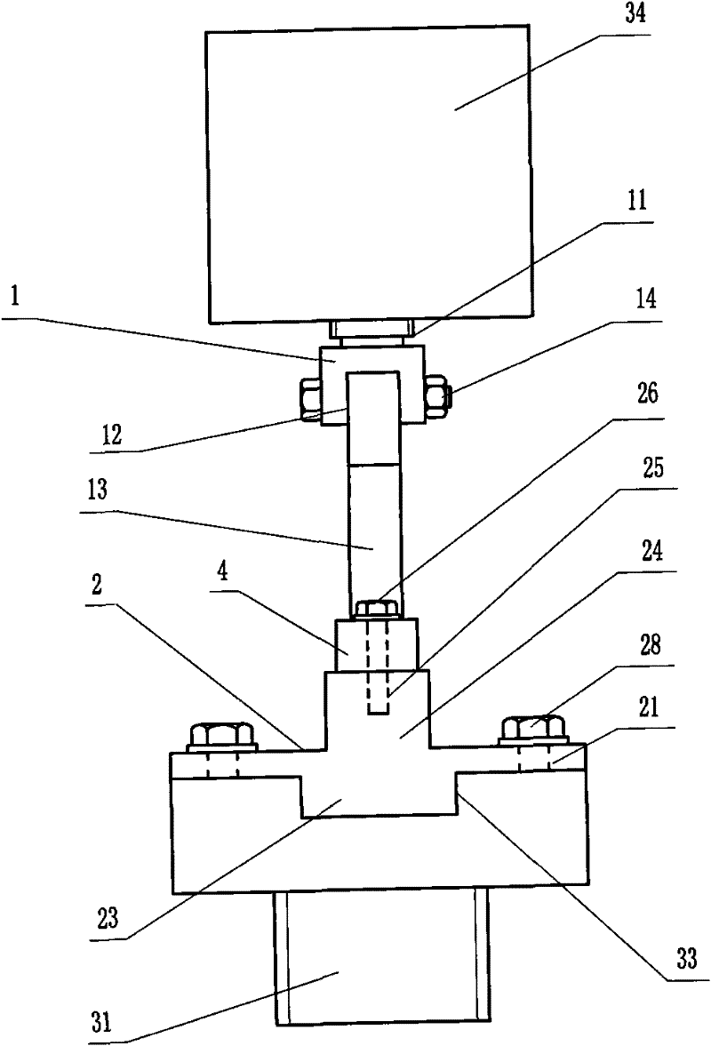
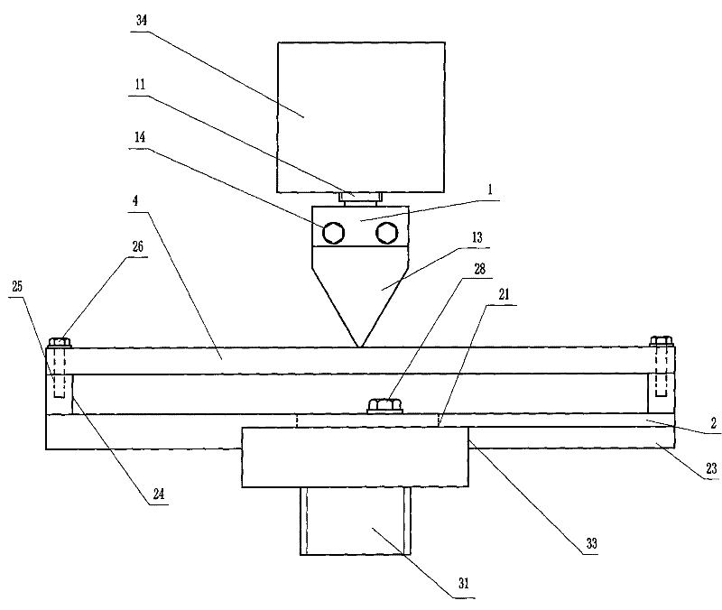
[0019] figure 1 , figure 2 As shown, a specific embodiment of the present invention is: a rail fatigue test fixture under the action of bending moment, including an upper fixture 1 and a lower fixture 2 . The upper part of the upper fixture 1 is the screw rod 11 threadedly connected with the experimental machine force sensor 34, and the lower part is a rectangular slot 12 with the opening downward. The flat top of the triangular loading head 13 is inserted into the rectangular slot, and passes through the rectangular slot 12 and the opening of the loading head 13. The screw 14 connects the upper fixture 1 with the loading head 13; the lower end of the loading head 13 is arc-shaped with a curvature radius of 1-10 mm. The lower fixture 2 is a rectangular platform. The lower fixture 2 is provided with a strip mounting hole 21 corresponding to the threaded mounting hole of the hydraulic cylinder 31 of the experimental machine. The bottom of the lower fixture 2 is provided with ...


PUM


Abstract

The invention relates to a clamp for a rail fatigue experiment acted by a bending moment. The upper part of an upper clamp thereof is provided with a threaded rod which is in threaded connection with a force sensor of an experiment machine, the lower part of the upper clamp is provided with a rectangular groove with a downward opening, the flattop part of a triangular loading head is inserted in the rectangular groove, and the upper clamp is connected with the loading head by a screw nail which respectively penetrates through the rectangular groove and the loading head; the lower end of the loading head is in the shape of a camber with the radius of curvature ranging from 1 to 10 mm; and a lower clamp is a rectangular platform, a strip mounting hole which corresponds to a threaded mounting hole of a hydraulic cylinder of the experiment machine is arranged on the lower clamp, a dummy club which is matched with a groove of a connection seat of the hydraulic cylinder of the experiment machine is arranged on the bottom of the lower clamp, both sides of the long edge of the upper surface of the lower clamp are provided with bulges, and threaded holes which are used for fixing samples are arranged on the bulges. The experiment clamp can better simulate the actual working condition of a steel rail in the process of service, and conveniently applies normal load to the steel rail, thereby enabling the rail fatigue experiment acted by the bending moment to be more accurately processed; and the experimental results can provide reliable and effective support for the material selectionand the design of the steel rail.

Description

Technical field: [0001] The invention belongs to the technical field of fatigue performance experiments of rail materials under the action of bending moment. Background technique: [0002] The rails are fixed on the sleepers by spikes, and the rails form a pair of fixed end contacts at every two sections of sleepers. When the wheel rolls on the rail, it will inevitably generate a normal load on the rail, and this normal load will cause the rail to be continuously subjected to the bending moment. That is to say, the normal load will cause the rail to produce downward bending deformation, that is, the lower area of ​​the rail is elongated by tension, and the upper area is shrunk by pressure; at this time, the energy dissipation is also different from that of pure tangential force. At the same time, if fatigue cracks initiate on the surface or subsurface of the rail, they will also be subjected to compression or tension. In this case, the bending moment will inevitably affect ...

Claims


Application Information

Patent Timeline
Patent Type & Authority Patents(China)
IPC IPC(8): G01N3/04G01N3/20
Inventor 钟雯胡家杰刘启跃石心余周仲荣
Owner SOUTHWEST JIAOTONG UNIV
Why Eureka
Try Eureka