Eureka AIR delivers breakthrough ideas for toughest innovation challenges, trusted by R&D personnel around the world.

Drum-type friction screw press

A technology of screw press and drum type, applied in the direction of presses, stamping machines, manufacturing tools, etc., can solve the problems of cost copper nut wear, large-scale development of presses, and reduce the efficiency of transmission machinery, etc., to prolong the service life and eliminate side force effect

Inactive Publication Date: 2009-12-30
SHANGHAI YUNLIANG FORGING PRESS
View PDF0 Cites 5 Cited by
  • Summary
  • Abstract
  • Description
  • Claims
  • Application Information

AI Technical Summary

Problems solved by technology

Since the rotation of the flywheel in a constant direction is caused by the friction wheel on one side, the screw will be subjected to a large lateral force during the movement, especially for the trapezoidal screw drive with a large pitch, the friction between the thread teeth will increase greatly , not only reduces the mechanical efficiency of the transmission, but also causes the expensive copper nuts to wear in one direction. Therefore, not only the existing presses cannot be developed towards large-scale

Method used


Image

  • Drum-type friction screw press

Examples


Embodiment Construction

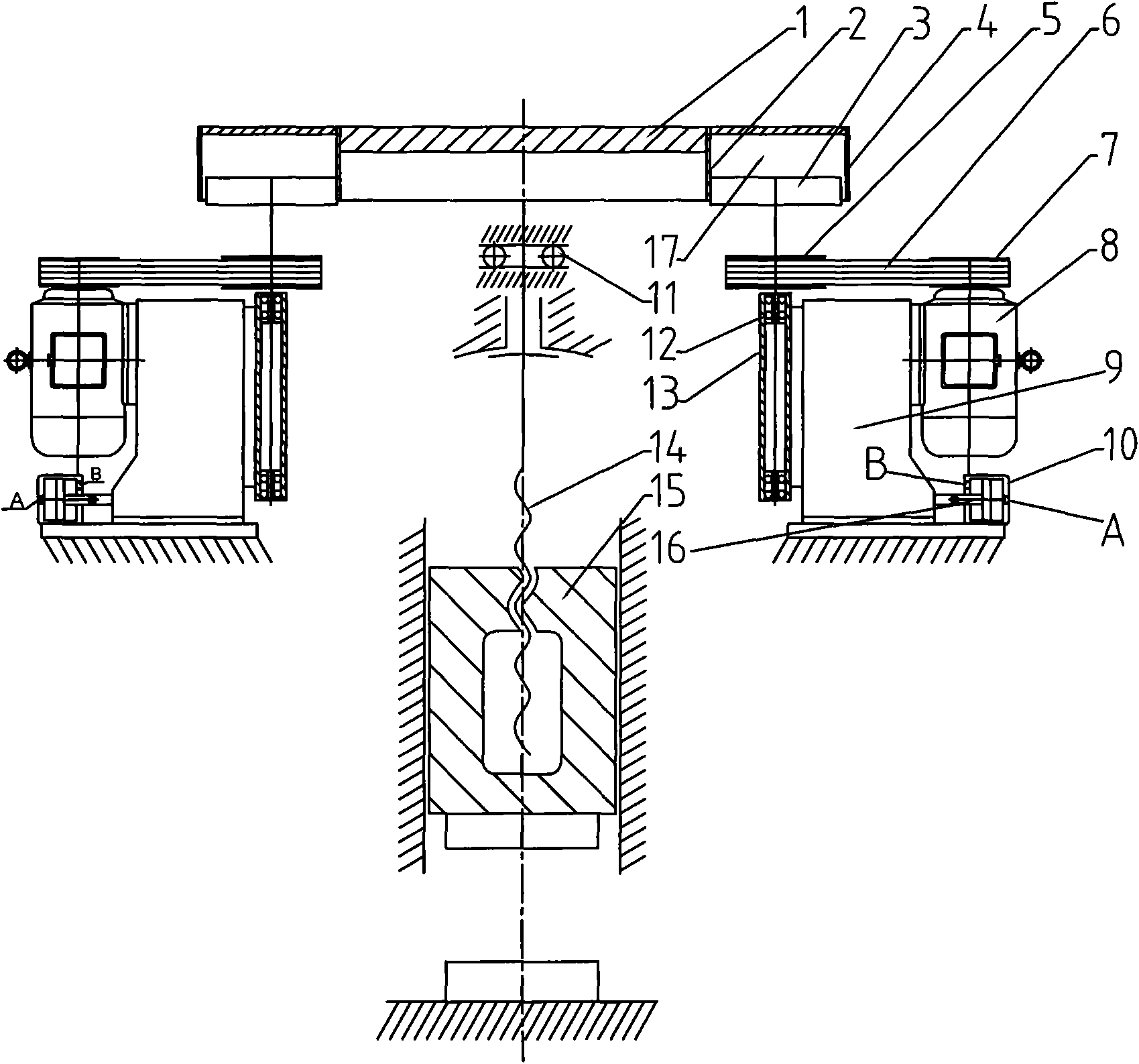
[0022] Such as figure 1 As shown, the drum type friction screw press includes a machine base 9, a horizontally rotating flywheel 1, the flywheel 1 is fixedly connected with the screw rod 14, and is rotationally connected with the machine base 9 through a plane bearing 11, the slider 15 is threadedly connected with the screw rod 14, and the slider 15 moves in the vertical direction, the flywheel 1 is rotated left or right by the action of the friction wheel 3, and the screw rod 14 drives the slider 15 to move up and down to implement the forging operation. An annular cavity 17 is provided inside the flywheel 1 , and the inner and outer walls of the cavity 17 respectively form the inner rim 2 and the outer rim 4 of the flywheel 1 . The cavity 17 is not closed, and an opening is provided below. Friction wheels 3 are arranged radially symmetrically in the cavity 17 , and there may be two, four, or eight friction wheels 3 . . . the number depends on the size of the flywheel 1 . T...


PUM


Abstract

The invention discloses a drum-type friction screw press, which belongs to a forge press machine. The drum-type friction screw press comprises a machine base and a horizontally rotating flywheel, wherein the flywheel is connected with a screw; the screw drives a sliding block to move up and down; the inside of the flywheel is provided with an accommodating cavity comprising the outer wheel rim and the inner wheel rim of the flywheel; friction wheels are radially and symmetrically arranged in the accommodating cavity; the friction wheels are driven by a motor through a belt to automatically rotate in the same direction; and the frication wheels are connected with a piston rod of an oil hydraulic cylinder and press the outer wheel rim and the inner wheel rim of the flywheel under the push of the piston rod respectively. For both the pressing and lifting of the sliding block, the friction wheels on the two sides oppositely press the flywheel with equal forces to rotate the flywheel. Thus, the drum-type friction screw press can eliminate the lateral force applied on the screw and prolong the service life of equipment.

Description

technical field [0001] The invention relates to a friction screw press used in forging machinery, in particular to a drum type friction screw press. Background technique [0002] The traditional friction screw press is a two-wheel drive mechanism in which a friction wheel is arranged on both sides of the flywheel, one is to press down the friction wheel, and the other is to lift the friction wheel. The working process of the press is as follows: the two friction wheels turn in the same direction. When one side of the friction wheel is close to contact with the flywheel, due to the effect of friction, it can drive the flywheel to rotate in one direction, thereby driving the screw to move; After the wheel comes into contact with the flywheel, it can also drive the flywheel to rotate in the opposite direction, thereby driving the screw to move in the opposite direction. The two friction wheels alternately press against each other and disengage the flywheel to realize the up an...

Claims


Application Information

Patent Timeline
Patent Type & Authority Applications(China)
IPC IPC(8): B30B1/22
Inventor 陆友荣龚伟兴陈洋清钱荣荣
Owner SHANGHAI YUNLIANG FORGING PRESS
Why Eureka
Eureka Blog
Learn More