Exciting circuit of flux gate sensor
A fluxgate sensor and excitation circuit technology, applied in the direction of logic circuit connection/interface layout, pulse shaping, etc., can solve problems such as difficulty in resonance adjustment, and achieve the effect of reducing residual magnetic error, reducing power consumption, and facilitating adjustment
- Summary
- Abstract
- Description
- Claims
- Application Information
AI Technical Summary
Problems solved by technology
Method used
Image
Examples
Embodiment 1
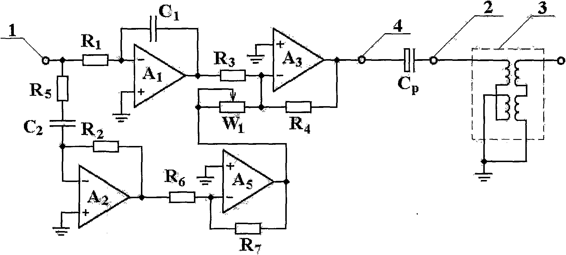
[0018] Embodiment 1: Fluxgate sensor excitation circuit containing inverting differentiator and inverting amplifier. refer to figure 1 .
[0019] (1) Resistance R 1 , capacitance C 1 and op amp A 1 connected as an inverting integrator;
[0020] (2) Resistance R 2 , resistance R 5 , capacitance C 2 and op amp A 2 connected as an inverting differentiator;
[0021] (3) Resistance R 6 , resistance R 7 and op amp A 5 connected as an inverting amplifier;
[0022] (4) Resistance R 3 , resistance R 4 , adjustable resistance W 1 and op amp A 3 Connected as an adder, the operational amplifier A 3 With power drive capability, the excitation voltage and excitation current generated by the circuit of this embodiment can be output without distortion;
[0023] (5) The input terminals of the integrator and the differentiator are connected together and connected with the input terminal 1 of the square wave signal;
[0024] (6) The output of the integrator and an input termi...
Embodiment 2
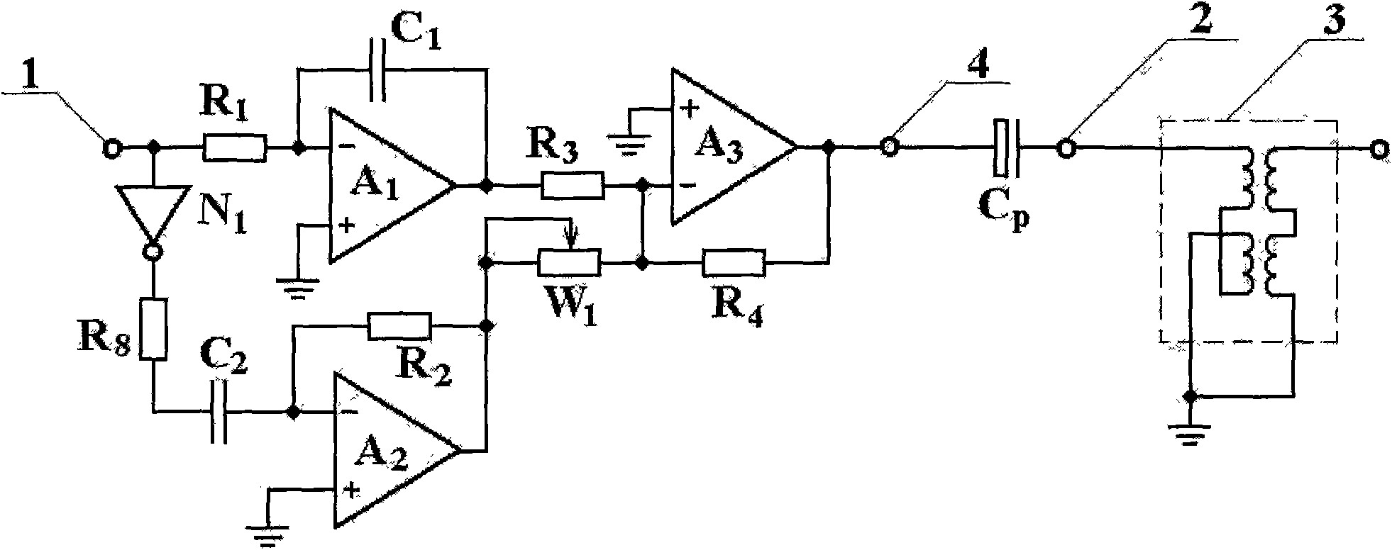
[0033] Embodiment 2: Fluxgate sensor excitation circuit with inverter and inverting differentiator. refer to figure 2 .
[0034] (1) Resistance R 1 , capacitance C 1 and op amp A 1 connected as an inverting integrator;
[0035] (2) Resistance R 2 , resistance R 8 , capacitance C 2 and op amp A 2 connected as an inverting differentiator;
[0036] (3) Resistance R 3 , resistance R 4 , adjustable resistance W 1 and op amp A 3 Connected as an adder, the operational amplifier A 3 With power drive capability, the excitation voltage and excitation current generated by the circuit of this embodiment can be output without distortion;
[0037] (4) The input terminal of the integrator is connected with terminal 1 of the input square wave signal;
[0038] (5) Terminal 1 of the input square wave signal passes through the inverter N 1 Connected to the input of the inverting differentiator;
[0039] (6) The output of the integrator and an input terminal R of the adder 3 Co...
Embodiment 3
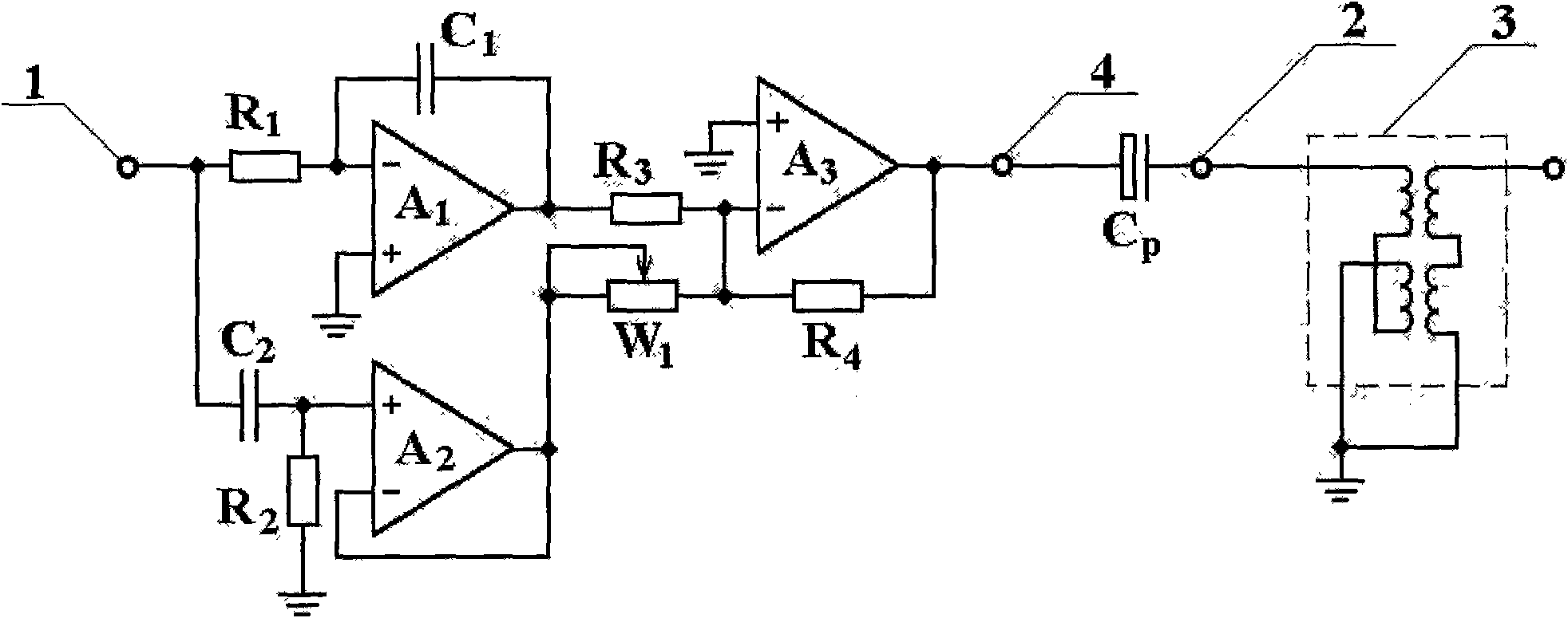
[0048] Embodiment 3: Fluxgate sensor excitation circuit with non-inverting differentiator. refer to image 3
[0049] (1) Resistance R 1 , capacitance C 1 and op amp A 1 connected as an inverting integrator;
[0050] (2) Resistance R 2 , capacitance C 2 and op amp A 2 connected as an in-phase differentiator;
[0051] (3) The input terminals of the integrator and the differentiator are connected together, and are connected with terminal 1 of the input square wave signal;
[0052] (4) Resistance R 3 , resistance R 4 , adjustable resistance W 1 and op amp A 3 Connected as an adder, the operational amplifier A 3 With power drive capability, the excitation voltage and excitation current generated by the circuit of this embodiment can be output without distortion;
[0053] (5) The output of the integrator and an input terminal R of the adder 3 Connection; the output of the differentiator and the other input of the adder W 1 connect;
[0054] (6) Resistance R 1 , ca...
PUM
| Property | Measurement | Unit |
|---|---|---|
| Capacitance | aaaaa | aaaaa |
Abstract
Description
Claims
Application Information
 - R&D
- Intellectual Property
- Life Sciences
- Materials
- Tech Scout
- Unparalleled Data Quality
- Higher Quality Content
- 60% Fewer Hallucinations
Browse by: Latest US Patents, China's latest patents, Technical Efficacy Thesaurus, Application Domain, Technology Topic, Popular Technical Reports.
© 2025 PatSnap. All rights reserved.Legal|Privacy policy|Modern Slavery Act Transparency Statement|Sitemap|About US| Contact US: help@patsnap.com


