
Rotary dynamic closed filtering process and device

A rotary dynamic filter device technology, applied in the direction of mobile filter element filter, filter separation, separation method, etc., can solve the problems of turbidity of filtrate, reduction of filtration efficiency, high cost of valve and control circuit, etc., and achieve the stability of internal sweeping flow field , Filtration process is continuous, and the service life is improved

Inactive Publication Date: 2009-12-16
徐柏根
View PDF0 Cites 6 Cited by
  • Summary
  • Abstract
  • Description
  • Claims
  • Application Information

AI Technical Summary

Problems solved by technology

However, there is such a problem in the automatic control technology of the slag liquid discharge end: it takes a certain period of time to open or close the valve at the discharge end, and the filter medium in the filter chamber needs to establish a new dynamic balance after opening and closing, and the filtrate is turbid at this time. Takes time to turn clear; high cost of valves and control lines; high risk of clogging failure
Moreover, the cantilever beam of the rotating impeller shaft of the current rotary dynamic filter is a one-way support structure. Although the advantage is that it is convenient to install impellers and filter plates one after another, the disadvantage is that the one-way support and the radial runout of the cantilever end make the filter The medium is easily damaged by the impeller, and the number of stages and diameters of the impeller and filter plate cannot be increased as much as possible, which reduces the filtration efficiency
In addition, the selection of filter media was originally limited to filter cloth. Although the rotary dynamic filter has a wider selection of materials, it is difficult to install and clean.
Moreover, the current rotary dynamic filter has high cost and high price, making it difficult for users to choose

Method used


Image

  • Rotary dynamic closed filtering process and device
  • Rotary dynamic closed filtering process and device
  • Rotary dynamic closed filtering process and device

Examples


Embodiment Construction

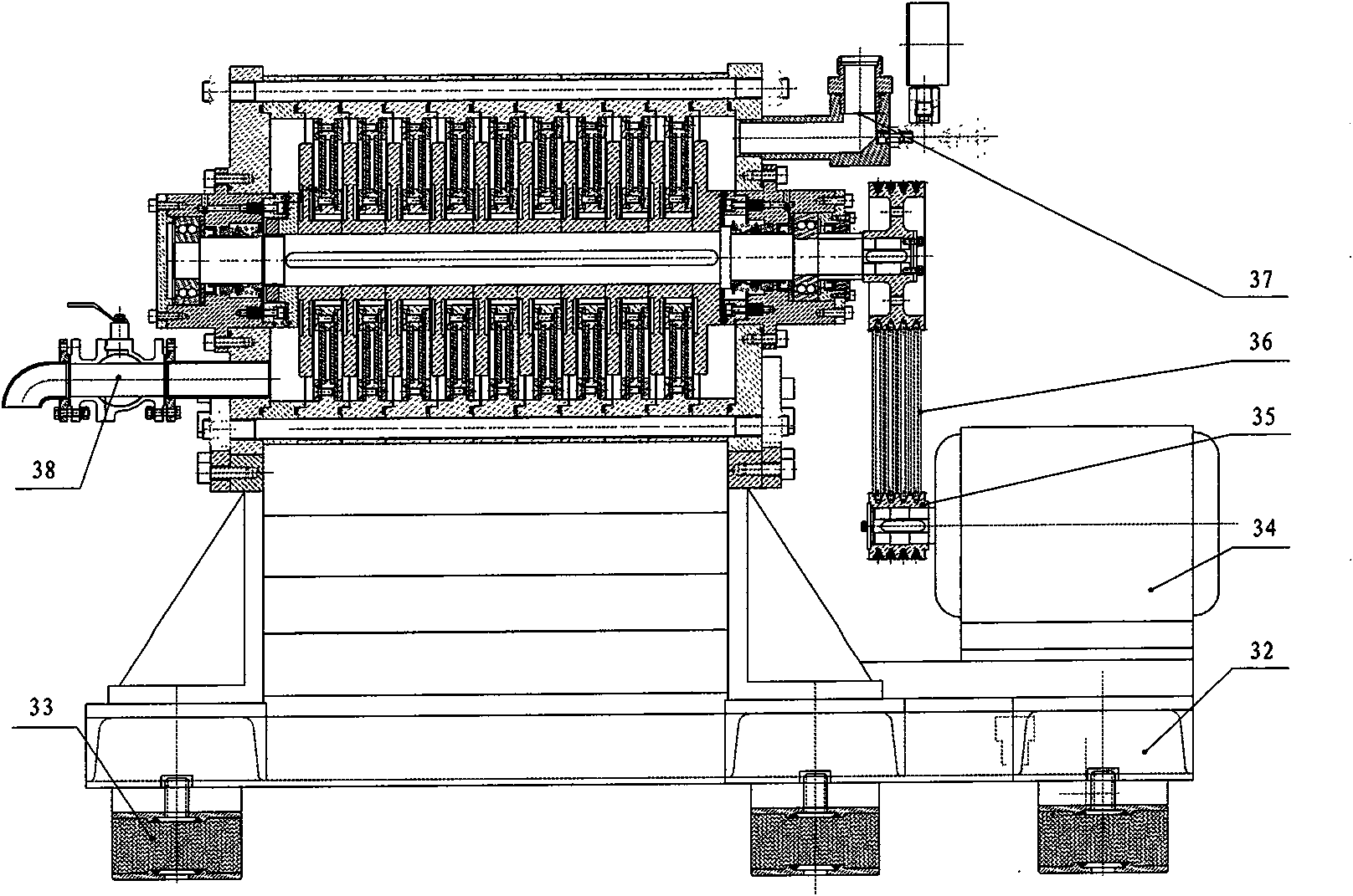
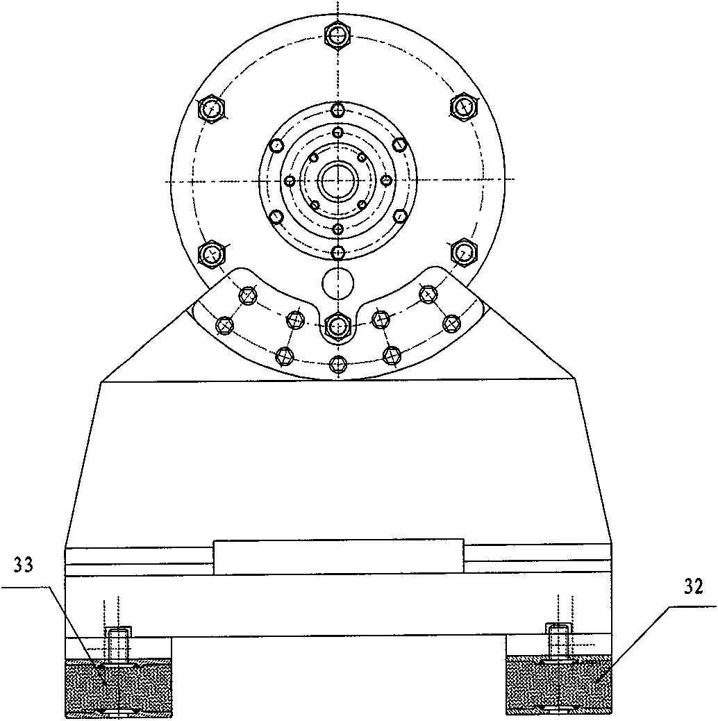
[0033] The present invention will be further described in detail below in conjunction with the accompanying drawings and embodiments.

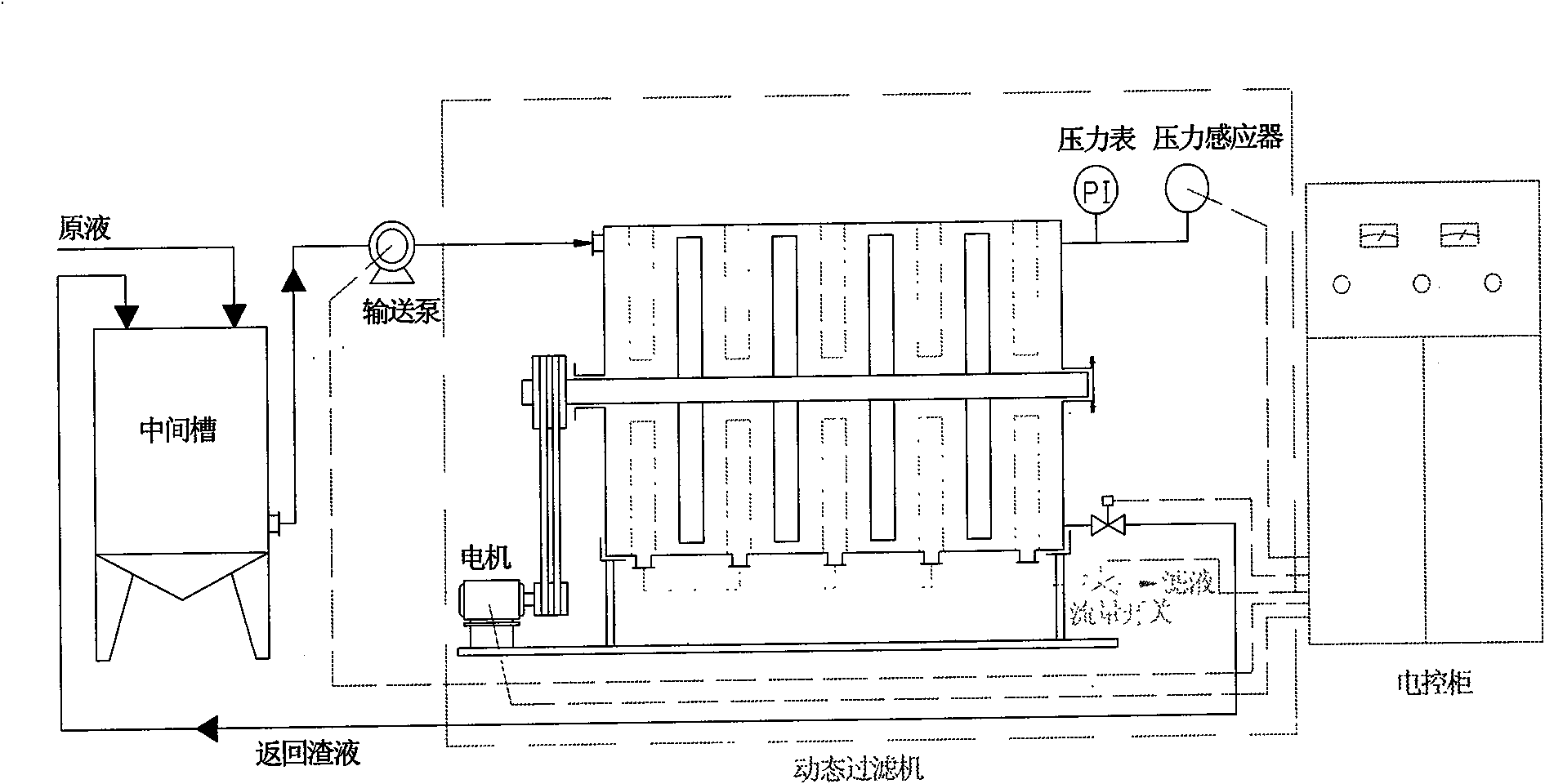
[0034] see figure 1, the filtration process of the present invention changes the valve of the slag liquid discharge port of the original filter from normally closed to normally open, and communicates with the middle tank, the filtrate discharge port is provided with a flow switch, and is connected with the electric control cabinet, and the delivery pump and the driving rotary impeller The running motor is also connected with the electric control cabinet. Firstly, the raw liquid, that is, the suspension to be filtered, or the mother liquid, is sent into the middle tank, that is, the liquid collection tank by self-flow or by pump; then the mother liquid in the middle tank is pressed into the filter chamber of the dynamic filter from the feed port through the delivery pump. , the filtrate is reused or discharged, and the slag is returned to the ...


PUM


Abstract

The invention belongs to the technical field of solid-liquid separation process and apparatus, in particular relates to a rotary dynamic closed filtering process and device. The invention provides a new dynamic circulation filtering process, which has the following key points that: mother solution, namely suspension to be filtered, is fed into one or a plurality of collecting tanks connected in parallel; a mother solution pump in the collecting tank is pressed to a filter chamber of a filtering machine, filtrate is either recycled or discharged, a residue filtrate discharge hole is normally opened, the residue filtrate is refluxed to the collecting tank via a pipeline; the mother liquid is ceaselessly circulated and filtered and the residue filtrate is ceaselessly concentrated, until the filtrate is discharged in zero amount or extremely small amount, an electric motor and a conveying pump of rotating impellers of the filtering machine are driven to cease operation; the residue filtrate in the collecting tank is completely drained and then the above steps are repeated over and over again. The invention employs process method of the closed circulation system, which is simple, reliable, continuous in the process of filtration, crystal-clear in filtrate and unchanged in the middle; and the service life of the filtering machine is remarkably prolonged.

Description

technical field [0001] The invention belongs to the technical field of solid-liquid separation technology and equipment, and in particular relates to a rotary dynamic closed filtration technology and device. Background technique [0002] With the continuous development of all walks of life in our country, the application of solid-liquid separation technology is becoming more and more extensive, from chemical industry to fine chemical industry, from mining to metallurgy, water conservancy and power generation, medicine and food to petroleum, machinery, electronics and various industrial sectors. First, there is no solid-liquid separation operation (either as the main or auxiliary), and the treatment of wastewater and sewage is inseparable from solid-liquid separation. As human beings cherish and utilize resources more, and have higher requirements for a beautiful environment and quality of life (while environmental pollution is becoming more and more serious), the solid-liqui...

Claims


Application Information

Patent Timeline
IPC IPC(8): B01D33/17
Inventor 徐柏根
Owner 徐柏根
Learn More