Pulser plate mounting structure
A pulse generator and structure technology, used in couplings, engine control, rigid shaft couplings, etc., can solve the problems of difficulty in improving the positioning accuracy of the pulse generator board, poor productivity, and long processing hours. High degree of freedom, good productivity, and productivity-enhancing effects
- Summary
- Abstract
- Description
- Claims
- Application Information
AI Technical Summary
Problems solved by technology
Method used
Image

Examples
no. 1 example
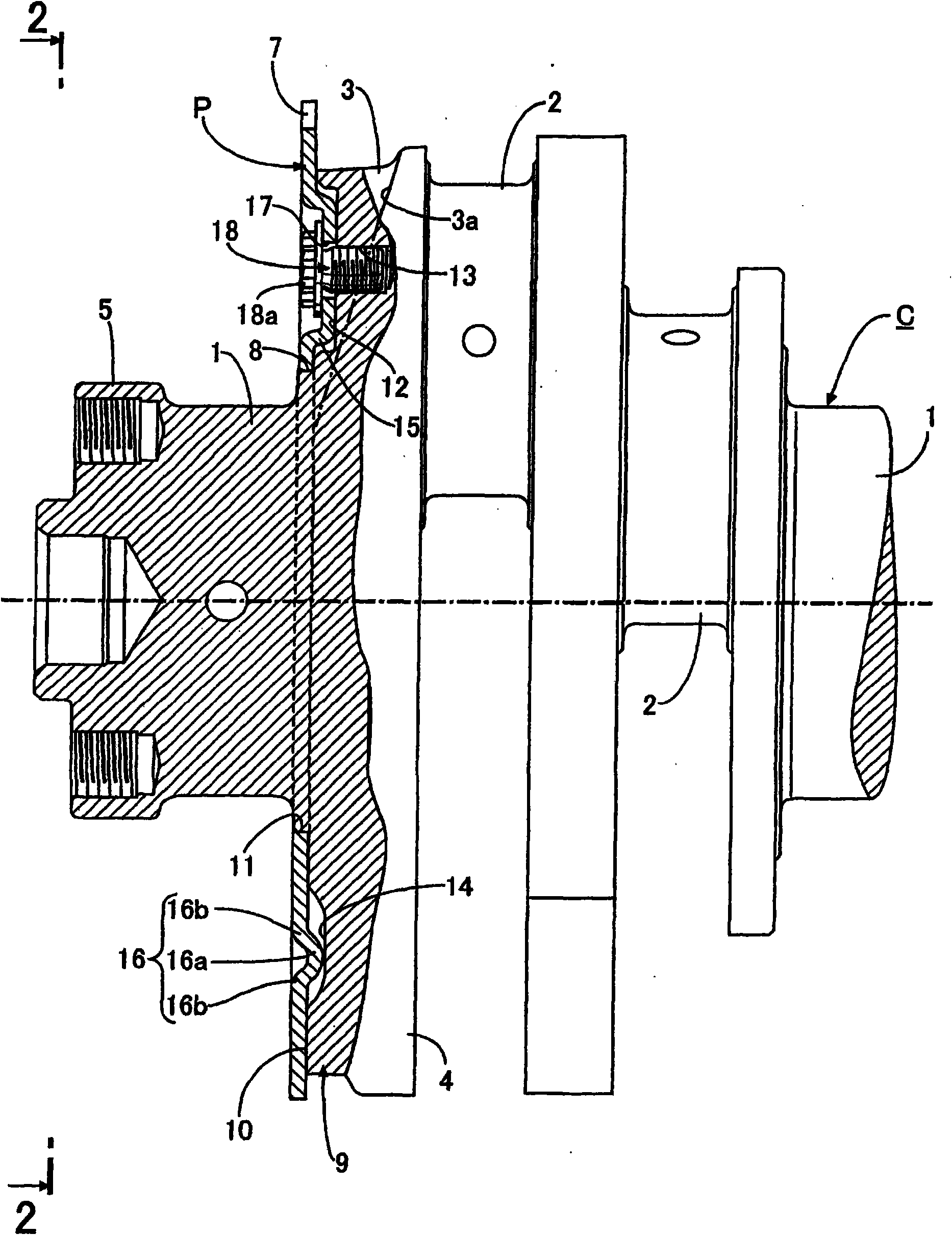
[0057] First, from Figure 1 ~ Figure 3 The description begins with the illustrated first embodiment of the invention. exist figure 1 and figure 2 Among them, the crankshaft C is a crankshaft for a multi-cylinder internal combustion engine, which has: a plurality of journals 1 supported by a plurality of main bearings of the crankcase; a plurality of crankpins 2 connected with the large ends of a plurality of connecting rods; and A plurality of crank arms 3 that are integrally connected between adjacent journals 1 and crank pins 2, and counterweights 4 are integrally connected to each crank arm 3, and the counterweights 4 are separated from the central axis of the journal 1. Extends in the opposite direction to the crank arm 3 . In addition, a flange 5 is formed at one end of the crankshaft C, and a driven member such as a crank pulley or a flywheel is bolted to the flange 5 .
[0058] Such as figure 2 As shown, the crank arm 3 is formed so that its width is narrow in t...
no. 2 example
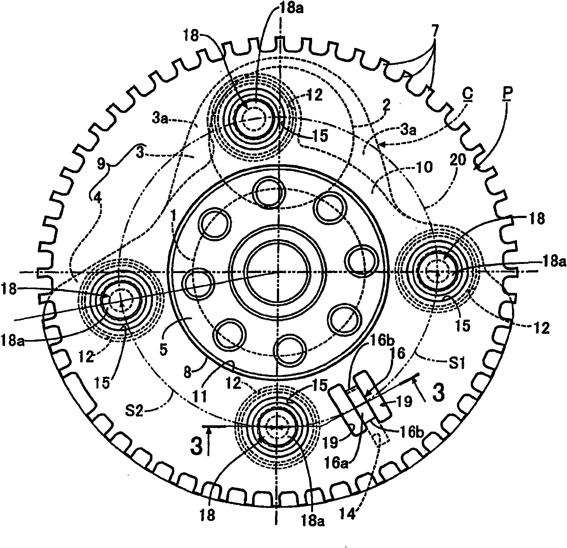
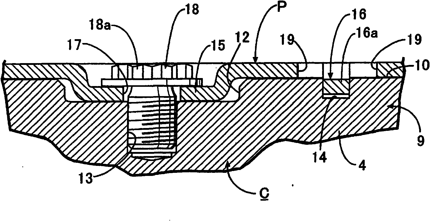
[0074] next, yes Figure 4 ~ Figure 7 A second embodiment of the invention is shown for illustration.
[0075] Each boss 15 of the pulse generator plate P is in the shape of a bottomed ellipse cylinder, and the short diameter D1 of the ellipse cylindrical portion 15a is along the circumferential direction A of the pulse generator plate P, and the long diameter D2 is along the circumference direction A of the pulse generator plate P. The radial direction B is configured.
[0076] However, the wall thickness of the pulse generator plate P produced by stamping is relatively thin. Therefore, when the torque of the crankshaft C fluctuates during the operation of the engine, the plate-shaped part between adjacent bosses 15 vibrates violently. In the second embodiment, since the cylindrical portion 15a of each boss 15 is formed such that the short diameter D1 is along the The circumferential direction A and major diameter D2 of the pulse generator plate P are along the elliptical c...
no. 3 example
[0079] next, yes Figure 8 A third embodiment of the invention is shown for illustration.
[0080] In this third embodiment, the cylindrical portion 15a of the boss 15 of the pulse generator plate P continuously connects a pair of arc wall portions 22 and a pair of straight wall portions 23 to form a small stamp shape in section, and the pair of circular The arc wall portions 22 face each other at a distance corresponding to the long diameter D2, and the pair of straight wall portions 23 face each other at a distance corresponding to the short diameter D1. At this time, similar to the above-mentioned embodiment, the cylindrical portion 15a of the boss 15 is arranged such that the short diameter D1 is along the circumferential direction A of the pulse generator plate P, and the long diameter D2 is along the radial direction B of the pulse generator plate P. configure. The structure other than that is the same as the above-mentioned second embodiment, therefore, in Figure 8 ...
PUM
 Abstract
Description
Claims
Application Information
 - R&D
- Intellectual Property
- Life Sciences
- Materials
- Tech Scout
- Unparalleled Data Quality
- Higher Quality Content
- 60% Fewer Hallucinations
Browse by: Latest US Patents, China's latest patents, Technical Efficacy Thesaurus, Application Domain, Technology Topic, Popular Technical Reports.
© 2025 PatSnap. All rights reserved.Legal|Privacy policy|Modern Slavery Act Transparency Statement|Sitemap|About US| Contact US: help@patsnap.com