Band-pass filter capable of suppressing second harmonic

A band-pass filter and second harmonic technology, applied to waveguide devices, circuits, electrical components, etc., can solve problems such as unfavorable design and processing, complex circuit structure, large circuit size, etc., and achieve simple structure and simple circuit structure , easy-to-achieve effects

Inactive Publication Date: 2009-12-09
PEKING UNIV
View PDF0 Cites 8 Cited by
  • Summary
  • Abstract
  • Description
  • Claims
  • Application Information

AI Technical Summary

Problems solved by technology

[0004] The above four methods have the following defects: the circuit size of methods (1) and (4) is relatively large, which brings inconvenience to the application; the circuit structure of methods (2) and (3) is complicated, which is not conducive to design and processing

Method used


Image

  • Band-pass filter capable of suppressing second harmonic
  • Band-pass filter capable of suppressing second harmonic
  • Band-pass filter capable of suppressing second harmonic

Examples


Embodiment 1

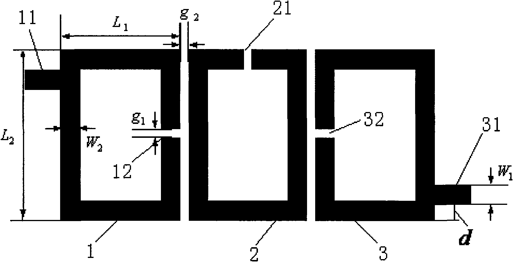
[0030] Embodiment one, such as figure 1 , Figure 6 As shown, in the bandpass filter of this embodiment, when the left open-loop resonator 1, the middle open-loop resonator 2 and the right open-loop resonator 3 are all rectangular, the left open-loop resonator 1 and the middle open-loop resonator The device 2 and the right open-loop resonator 3 are etched on one side of the dielectric substrate 5 at equal intervals, and the other side of the dielectric substrate 5 is a ground plate 6 . The dielectric constant of the dielectric substrate 5 is usually between 4-10.

[0031] The bandpass filter design steps of the present embodiment are as follows:

[0032] 1) The dielectric constant of the selected dielectric substrate 5 is 6.03, the thickness is 32 mils, and the microstrip line width W of the input port 11 and the output port 31 1 =1.2mm, the center frequency of the passband of the bandpass filter is f=1.1GHz. The length L of the half-wavelength microstrip resonator OL of t...

Embodiment 2

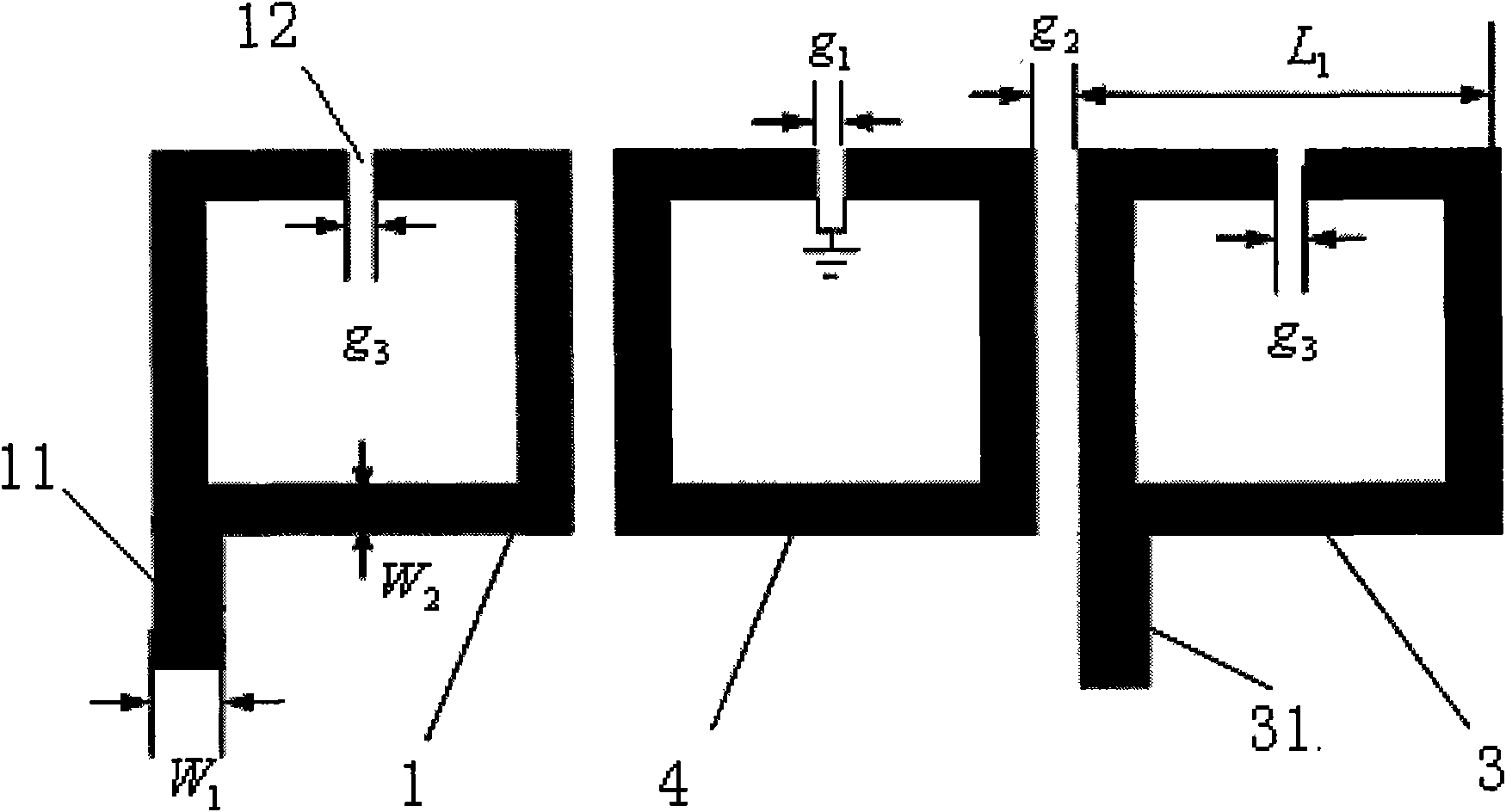
[0036] Embodiment two, such as figure 2 , Figure 6 As shown, the bandpass filter includes a left open-loop resonator 1, a short-circuited ring resonator 4 and a right open-loop resonator 3, and the left open-loop resonator 1, the short-circuited ring resonator 4 and the right open-loop resonator 3 are of the same size The square is etched on one side of the dielectric substrate 5 at equal intervals, and the open-loop port of the short-circuit ring resonator 4 is drilled and grounded, and is arranged between the left open-loop resonator 1 and the right open-loop resonator 3 . Wherein, the open-loop slits of the three resonators are all arranged at the center of the top edge of the resonators, and the widths of the open-loop slits are the same. The other side of the dielectric substrate 5 is a ground plate 6 . The dielectric constant of the dielectric substrate 5 is usually between 4-10.

[0037] The bandpass filter design steps of the present embodiment are as follows:

...


PUM


Abstract

The invention relates to a band-pass filter capable of suppressing second harmonic and is characterized in that the filter comprises a left open ring resonator, a middle open ring resonator and a right open ring resonator which have the same rectangle rings, the rectangle rings are composed of microstrip lines, the perimeter of the unwrapped microstrip lines is half of the working wavelength; theleft open ring resonator, the middle open ring resonator and the right open ring resonator are arranged on a substrate of medium side by side in the same interval; the input port of the left open ring resonator and the output port of the right open ring resonator are distributed symmetrically for the middle open ring resonator, the width of the microstrip transmission line is 50 ohm; open-loop gaps are arranged at the midpoint of each located side. The band-pass filter capable of suppressing second harmonic of the invention has simple structure and is easy to realize, the requirement on dielectric-slabs of the band-pass filter is not high and no lumpedelement is contained in the band-pass filter, so that no heat energy can be generated by resistance and the band-pass filter has wide application prospect in radio frequency integrated circuits.

Description

technical field [0001] The invention relates to a band-pass filter, in particular to a band-pass filter capable of suppressing the second harmonic. Background technique [0002] Band-pass filter is a very important device in microwave system. Band-pass filter is a device that allows waves of a specific frequency band to pass while shielding other frequency bands. An ideal bandpass filter should have a smooth passband while restricting the passage of waves of all frequencies outside the passband. However, in the prior art, most bandpass filters have harmonic response characteristics, which will cause microwave A decrease in overall system performance. [0003] At this stage, the methods of suppressing harmonic response can be roughly divided into four categories: (1) Connect a band-stop filter to the band-pass filter so that the center frequency of the latter’s stop band coincides with the second harmonic frequency of the former , the harmonic response of the bandpass filte...

Claims


Application Information

Patent Timeline
Patent Type & Authority Applications(China)
IPC IPC(8): H01P1/212
Inventor 戴高乐夏明耀
Owner PEKING UNIV
Why Eureka
Try Eureka