
Winding device and winding method

A winding device and wire material technology, which is applied in electromechanical devices, coil manufacturing, and motor generator manufacturing, etc. It can solve the problems that the motor cannot follow the rotation speed of the head support shaft, and cannot stabilize the winding of the stator magnetic pole.

Active Publication Date: 2009-11-25
NITTOKU ENG CO LTD
View PDF1 Cites 22 Cited by
  • Summary
  • Abstract
  • Description
  • Claims
  • Application Information

AI Technical Summary

Problems solved by technology

At this time, the shaft rotation motor of the cable shaft may not be able to follow the rotation speed of the head support shaft, and the wire may not be stably wound to the stator poles.

Method used


Image

  • Winding device and winding method
  • Winding device and winding method
  • Winding device and winding method

Examples


Embodiment Construction

[0013] Hereinafter, embodiments of the present invention will be described with reference to the drawings.

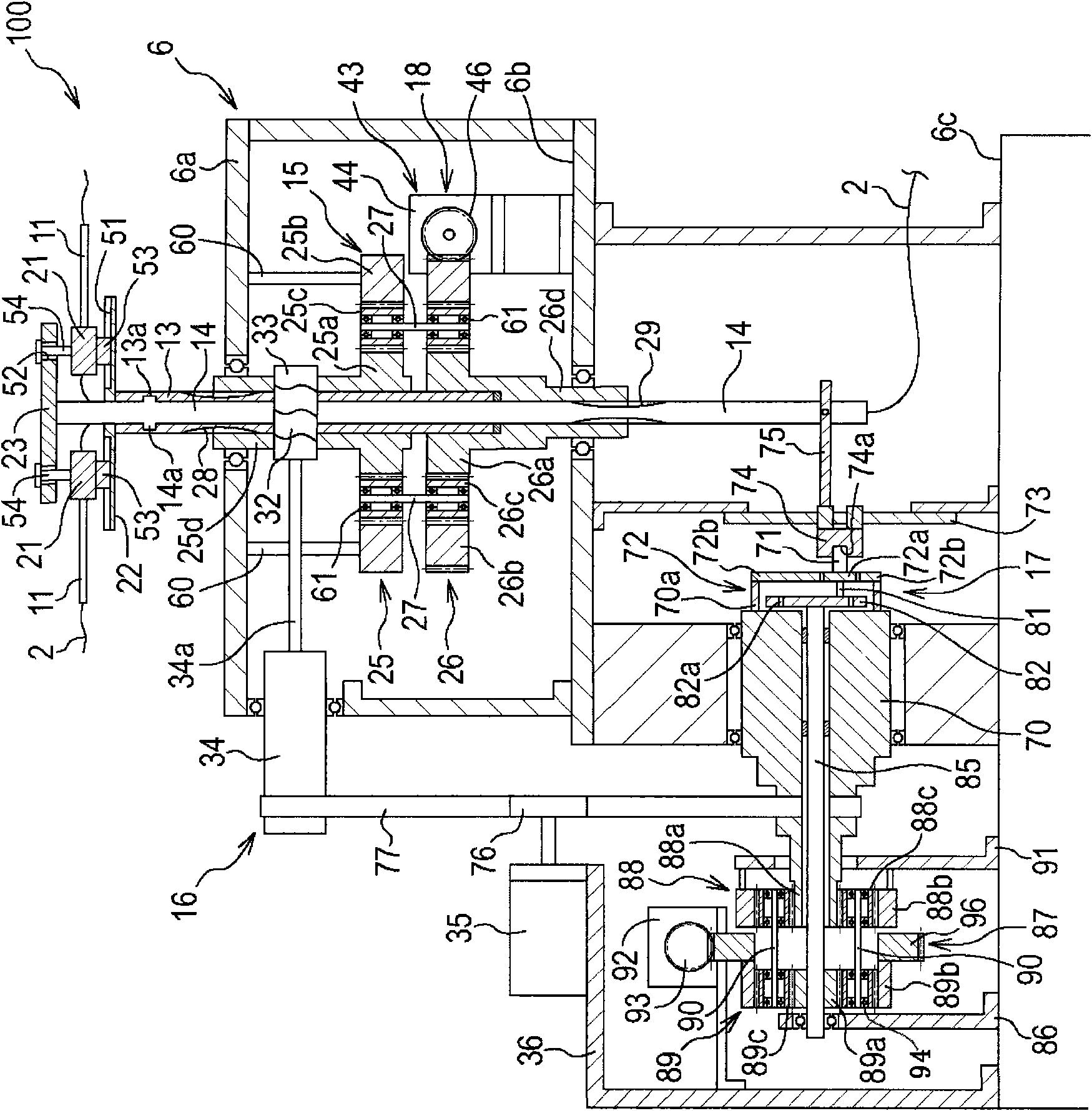
[0014] refer to Figure 1 ~ Figure 3 , the winding device 100 according to the embodiment of the present invention will be described.

[0015] The winding device 100 is a device for automatically winding the wire 2 on the magnetic pole 1 . In this embodiment, an apparatus for winding the wire 2 around the magnetic poles 1 of the stator 3 in the inner rotor type motor will be described.

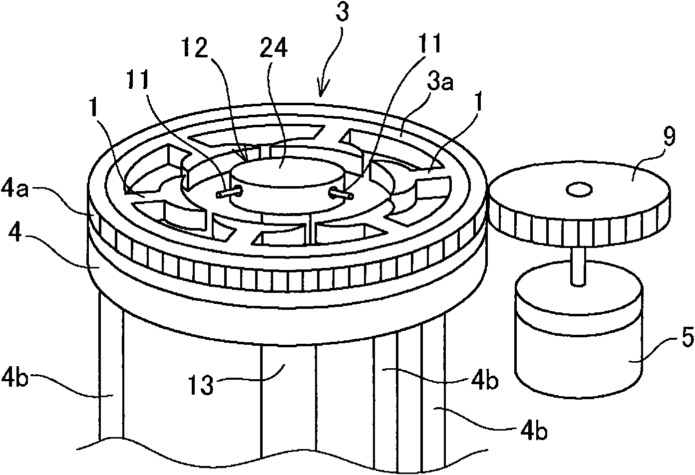
[0016] Such as figure 1 As shown, the stator 3 is supported by the stator supporting platform 4, and the indexing motor 5 drives the stator supporting platform 4 to rotate. The stator supporting platform 4 is arranged on the upper layer 6a of the bracket 6 through the support 4b (refer to figure 2 ), the indexing motor 5 is also arranged on the upper layer 6a. And, in figure 2 as well as image 3 In FIG. 2 , illustration of the stator 3 , the stator supporting base 4 , and the ...


PUM


Abstract

The invention provides a winding device and a winding method. The winding device for winding wires on a magnetic pole comprises a head, a head supporting shaft, a traverse shaft, a shaft connecting mechanism, a head rotating mechanism, a nozzle moving mechanism and a head moving mechanism, wherein the head is used for supporting a nozzle; the head supporting shaft is used for supporting the head; the rotation of the traverse shaft around a shaft center is relatively independent from the head supporting shaft, and the traverse shaft is connected with the head supporting shaft along an axial direction; the shaft connecting mechanism is connected with the head supporting shaft and the traverse shaft to enable the rotation to be transferred to the traverse shaft by enabling the head supporting shaft to rotate around the shaft center, and the rotation can not be transferred to the head supporting shaft even the traverse shaft rotates around the shaft center; the head rotating mechanism enables the traverse shaft and the head supporting shaft to synchronously rotate and enables the head to rotate around the shaft center by enabling the head supporting shaft to rotate; the nozzle moving mechanism enables the traverse shaft to rotate relative to the head supporting shaft and enables the nozzle to move along the axial direction by enabling the traverse shaft to rotate; and the head moving mechanism enables the head to move along the axial direction by enabling the head supporting shaft and the traverse shaft to move along the axial direction.

Description

technical field [0001] The invention relates to a winding device and a winding method, in particular to a winding device and a winding method for manufacturing a stator coil. Background technique [0002] Japanese Patent Laid-Open No. 2002-208530 discloses a winding device for manufacturing stator coils. [0003] The winding device described in Japanese Patent Application Laid-Open No. 2002-208530 includes: a head support shaft that rotates the head of the supporting nozzle; a cable shaft that rotates relative to the head support shaft; a shaft rotation motor that rotates the above-mentioned shafts; The guide plate provided at the end of the head support shaft; the cam plate provided at the end of the cable shaft; and the nozzle holder, which has: a sliding part that can be slidably engaged in the guide groove of the guide plate and engaged with the cam plate The cam follower of the cam slot. [0004] In this bobbin winding device, if the respective shaft rotating motors a...

Claims


Application Information

Patent Timeline
IPC IPC(8): H02K15/08H02K15/095H01F41/06
Inventor 内藤敬治
Owner NITTOKU ENG CO LTD
Learn More