Accelerating device

A technology of acceleration device and driving roller, which is applied in entertainment, tracks for toys, toys, etc., can solve the problems of difficult adjoining setting, inability to launch toy vehicles straight, etc. progressive effect

Active Publication Date: 2013-04-03
TOMY CO LTD +1
View PDF3 Cites 0 Cited by
  • Summary
  • Abstract
  • Description
  • Claims
  • Application Information

AI Technical Summary

Problems solved by technology

If the two drive rollers are not synchronized, the toy vehicle cannot be launched straight
In addition, when using a pair of driving rollers to sandwich the two side surfaces of the toy vehicle and launch the toy vehicle straightly, space for the driving rollers is required on both sides of the running path. Therefore, it is difficult to arrange a plurality of driving paths adjacent to each other.

Method used


Image

  • Accelerating device
  • Accelerating device
  • Accelerating device

Examples


no. 1 approach

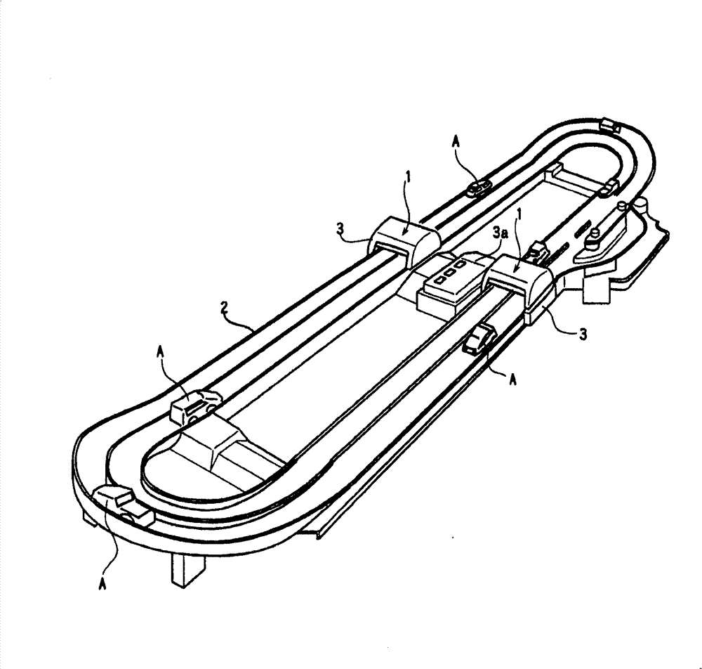
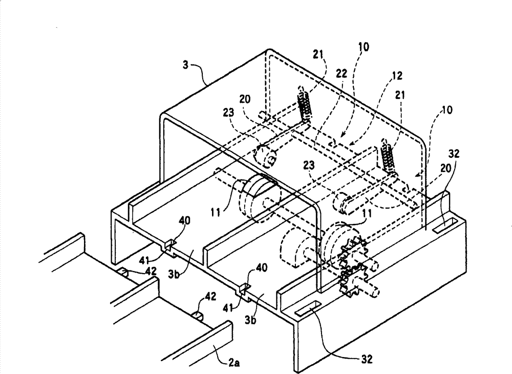
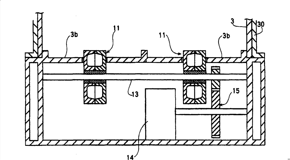
[0055] figure 1 It is a perspective view showing a ring track model equipped with an accelerator device of the present invention, figure 2 is a perspective view schematically showing the acceleration device, image 3 is a cross-sectional view schematically showing a drive mechanism of a power source and a drive roller, Figure 4 is a sectional view of the drive roller, Figure 5 is a cross-sectional view showing the launching method of the toy vehicle, Figure 6 It is a figure which shows an example of the drive circuit of a motor, Figure 7 is a diagram showing an example of a sound generating circuit.

[0056] figure 1 A circular orbit model to which the accelerator device of the embodiment is applied is shown in . The ring rail model 2 has the following structure: two doors 3 are provided, and rail members 2a constituting a straight running path or a curved running path are appropriately connected to the two doors 3 (refer to figure 2 ).

[0057] The main part of t...

no. 2 approach

[0091] use Figure 8 A second embodiment will be described. The same reference numerals are assigned to the same components as those in the first embodiment, and description thereof will be appropriately omitted.

[0092] exist Figure 8 , a travel path with a ramp is shown. This travel path is constituted by appropriately connecting a plurality of rail members.

[0093] The travel path has an uphill ramp 61 . A travel route constituting this uphill slope 61 is formed in a tunnel 80 . The tunnel 80 has a rail casing 80 a that covers the travel path from above and is detachable. The rail casing 80a is detachable.

[0094] In the tunnel 80 , seven sets of drive rollers 11 and dancer rollers 23 are provided along the traveling path 61 . Among them, the dancer roller 23 is arranged on the tunnel shell 80a. In addition, this second embodiment is configured to climb the toy vehicle A along the upward slope 61 via the seven drive rollers 11 and the dancer rollers 23 .

[009...


PUM


Abstract

The invention provides an accelerating device capable of straightly projecting toy vehicles. The accelerating device has: an accelerating area, having a part of driving paths of toy vehicles; a drive roller, a part of which is extended out above the driving paths of the accelerating area, and the outer peripheral face of which is abutted with the bottom surface of the toy vehicle entering the accelerating area; a motor, as the power source of the drive roller; and a force application mechanism installed at the accelerating area so that the toy vehicle positioned on the driving path is in compression joint with the drive roller from the above. The accelerating device is such configured that the toy vehicle entering the accelerating area is accelerated and projected out by means of the combined action of the drive roller and the force application mechanism. The invention is characterized in that the accelerating device has: a cover member provide with an entrance and an exit of the toy vehicles and capable of assembling and unassembling, which can prevent the hand from inserting the drive roller in an assembly state; and a cover member detection mechanism for detecting whether the cover member is in the assembly state, and enabling the driver of the drive roller to stop when the cover member is not in the assembly state.

Description

technical field [0001] The present invention relates to speed-up devices, and more particularly to speed-up devices for toy vehicles. Background technique [0002] There are, for example, the following Patent Documents 1 to 3 as accelerators that drive a driving roller with a motor, and launch a toy vehicle through the driving roller to run. In the launching devices of these patent documents, a part of a pair of drive rollers arranged in parallel to the shafts is arranged to face the side of the travel path, and the toy vehicle is sandwiched from both sides of the toy vehicle by the drive rollers. to launch the toy vehicle. [0003] [Patent Document 1] U.S. Patent Specification No. 5,299,969 (cf. Figure 5 ) [0004] [Patent Document 2] U.S. Patent Specification No. 5,899,789 (cf. image 3 ) [0005] [Patent Document 3] U.S. Patent Specification No. 6,695,675 (cf. Figure 2 ~ Figure 4 ) [0006] However, when the toy vehicle is launched straightly with both side surfac...

Claims


Application Information

Patent Timeline
Patent Type & Authority Patents(China)
IPC IPC(8): A63H18/00
Inventor 长坂好造渡边広幸柿崎克美流石正
Owner TOMY CO LTD
Why Eureka
Try Eureka